Sea-Pol
| Deployment Type | Ship/Land-deployable, containerized |
|---|---|
| Frequency | 5.65 GHz (C-band) |
| Operating Modes | STSR, LDR |
| Range Resolution | 54-300m |
| Typical Range | 120-300 km |
| Antenna | 4.3m (1 °) |
| Transmitter | Coaxial Magnetron (250 kW) |
| Receiver | Vaisala RVP9 |
 |
|
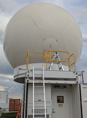
The CSU Sea-Pol ship- and land-deployable radar measures dual-polarization data over a range in excess of 200 km. It is designed for operation aboard Global-class research ships operated by the US oceanographic community, and has also been successfully operated on land-based deployments. The radar operates at C-band (5.65 GHz) and has a 4.3m stabilized antenna system.
The radar features dynamic platform stabilization, allowing it to perform earth-relative scanning strategies even on a moving platform such as a ship on the open ocean. A state of the art RVP900 digital signal processor outputs dual-polarization moment data, and provides the IRIS radar user interface.
The radar is packaged into two sub-assemblies, the radar shelter and the antenna platform. The radar shelter is housed in a 20' ISO container for ease of transportation and mounting onto research ships. The antenna platform is designed to mate to the top of the radar shelter, and holds the antenna positioner, antenna and radome.
CSU Sea-Pol is a part of the National Science Foundation's Community Instruments and Facilities Program, and may be requested through that program. When not deployed in the field, the radar is based at the CSU-CHILL main site in Greeley CO.
Technical Overview
Transmitter
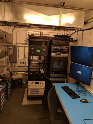
The radar transmitter uses a 250 kW coaxial magnetron tube, coupled to a solid-state modulator with multiple selectable pulse widths. A programmable logic controller (PLC) based control system sends commands to the modulator, and monitors its status. The transmitter is capable of a maximum duty cycle of 0.12%, with selectable pulse widths and programmable PRFs. Built-in monitoring circuitry reports faults such as arcs within the magnetron, waveguide under-pressurization and cooling subsystem failure. The output of the transmitter is fed through a high-power isolator to protect the magnetron against faults in the waveguide run to the antenna. A combined dehydrator and pressurization unit ensures that the waveguide is filled with dry air (-20 °C dew point) pressurized to at least 350 mbar to avoid arcing due to the high electric fields.
The waveguide assembly connects the transmitter to the antenna subsystem. This includes a pair of rotary joints that are used to traverse the azimuth and elevation axes of the positioner.
A simplified block diagram of the transmitter subsystem is shown below.

Receiver
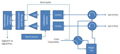
The radar receiver subsystem is mounted behind the antenna, in order to minimize the number of waveguide rotary joints and to improve the noise figure of the radar receiver. The receiver consists of two major parts, namely the antenna mounted receiver (AMR) and waveguide pallet. The AMR contains the low noise amplifiers, analog down-conversion stages, calibration subsystem and the intermediate frequency digital receiver (IFDR).
The AMR is housed in a temperature-controlled enclosure in order to keep all the active microwave components at a relatively constant temperature to avoid thermally induced drifts. Three receiver channels are provided, two for the vertical and horizontal polarization channels and one for the burst pulse channel, which is used to sample the magnetron pulse to implement coherent-on-receive. The AMR includes signal routing switches to implement receiver calibrations by injecting power from a calibrated noise source into the receiver front-end. Since the receiver bandwidth is entirely set by the digital filters implemented in the IFDR, the expected thermal noise may be used to compute the receiver gain. Digital output data from the IFDR is converted to a single-mode fiber optic signal, which traverses the azimuth axis via a fiber-optic rotary joint.
The waveguide pallet contains a waveguide switch, magic-tee, circulators and limiters. The switch permits operation in either horizontal transmit mode or simultaneous H and V transmit mode. In either case, both polarization channel receivers remain active, and may be used to measure depolarization ratios of the targets. The design minimizes noise figure of the radar by virtue of having the LNAs close to the antenna.
A simplified block diagram of the receiver subsystem is shown below.
Antenna, radome and stabilized positioner system
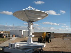
Sea-Pol uses a 4.3 meter diameter reflector antenna. The reflector assembly is made of fiberglass to make it light-weight and easy to handle. The antenna uses a dual linear polarization feed horn to generate a pencil beam of 1° beam width. The reflector can be disassembled into five pieces to fit within the 2.5 meter maximum allowed width inside an ISO container. The spars holding the feed horn are equipped with precision locating pins to allow repeatable performance between successive installations of the radar.
The two-axis antenna positioner allows positioning of the antenna in azimuth and elevation. Elevation travel is from -8° to +85°, with continuous rotation in azimuth. Waveguide rotary joints allow the transmitter pulse to traverse the rotation axes. The azimuth rotary joint also includes a fiber-optic channel and slip rings for radar data and control signals. Servo amplifiers accept commands from the radar controller to move the antenna at up to 30°/s. The drives are tuned for high accelerations and quick response time, which permits the dynamic repositioning required for antenna stabilization at sea. Two 17-bit absolute encoders are used to sense the antenna position.
An Inertial Navigation Unit (INU) measures both the static and dynamic pitch and roll of the radar platform. Static heading is also measured through the use of differential GPS. This information is used to offset the scanning plane of the radar by adjusting the elevation axis on a continuous basis during plan-position indicator (PPI) scans. The measured heading information is used to correct the azimuth angles so that the radar always makes measurements in earth-relative coordinates. In addition to the coordinate transformation between the two coordinate systems, the roll and pitch rates are used to compute a dynamic elevation angle adjustment such that the error between commanded and actual earth-relative elevation angle is minimized.
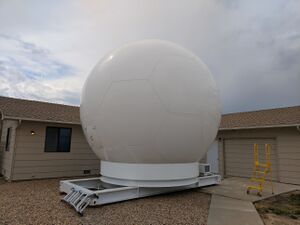
The antenna and positioner are enclosed within a fiberglass radome. The radome has a truncated icosahedron geometry, comprising pentagonal and hexagonal panels that are bolted together. This permits the large diameter (5.5 meters at equator) radome to be broken down for transport into pieces small enough to fit inside a standard ISO shipping container. The outside of the radome is covered with hydrophobic paint to avoid formation of water films that can lead to attenuation and distortion of dual polarization parameters.
The radome is humidity-controlled using a radome dehydrator system. This uses a refrigeration system to cool the intake air from the radome, causing moisture to condense out. The cool air is then reheated using the waste heat from the refrigeration system and pumped back into the radome in a closed cycle.
Deployments
Sea-Pol has deployed around the globe on various ship- and land-deployments.

PICCOLO 2024
Sea-Pol will be deployed as part of the Process Investigation of Clouds and Convective Organization over the atLantic Ocean (PICCOLO) 2024 field campaign. Sea-Pol will be deployed on the R/V Meteor, sailing from Cape Verde to Barbados through the Atlantic ITCZ on a six-week cruise. PICCOLO is a part of the larger Organized Convection and EarthCare Studies over the Tropical Atlantic (ORCESTRA) 2024 field campaign.

PRECIP-2022
Sea-Pol was deployed to Yonaguni Island, Okinawa, Japan in 2022 in support of the Prediction of Rainfall Campaign in the Pacific (PRECIP) 2022 field campaign. This campaign was sponsored by the National Science Foundation, and involved multiple Universities, agencies and instruments.
PISTON-2, 2019
Sea-Pol was deployed aboard the R/V Sally Ride in support of the Propagation of Intra-Seasonal Tropical OscillatioNs (PISTON-2) field campaign. The cruise departed from and returned to Keelung port, Taiwan. The campaign was sponsored by the Office of Naval Research (ONR).
PISTON, 2018
Sea-Pol was deployed aboard the R/V Thomas G Thompson in support of the Propagation of Intra-Seasonal Tropical OscillatioNs (PISTON) field campaign. The cruise departed from and returned to Kaohsiung, Taiwan, with a mid-cruise stop at Palau. The campaign was sponsored by the Office of Naval Research (ONR).
SPURS-2, 2017
Sea-Pol was deployed aboard the R/V Revelle in support of the Salinity Processes in the Upper Ocean Regional Study (SPURS-2) field campaign. The cruise departed from and returned to San Diego, California. The campaign was sponsored by the National Science Foundation and NASA.
Gallery
-
Sea-Pol deployed at CSU-CHILL, July 2017
-
Sea-Pol testing at CSU-CHILL, June 2017
-
Sea-Pol deployed at CSU-CHILL, July 2017
-
Sea-Pol deployed at CSU-CHILL, July 2017
-
Sea-Pol deployed on the R/V Revelle, October 2017
-
Sea-Pol under construction in Kaohsiung, TW, August 2018
-
Sea-Pol installed on the R/V Thomas Thompson August 2018
-
Sea-Pol installed on the R/V Sally Ride in Keelung, TW, August 2019
-
R/V Sally Ride with Sea-Pol sailing from Keelung, TW, September 2019
-
Sea-Pol deployed in Yonaguni, JP, May 27 2022
External Links
References
- J. George et al., "Salient features of the CSU sea-pol radar," 2018 IEEE Radar Conference (RadarConf18), Oklahoma City, OK, USA, 2018, pp. 1307-1310
- Rutledge, S. A., V. Chandrasekar, B. Fuchs, J. George, F. Junyent, B. Dolan, P. C. Kennedy, and K. Drushka, 2019b: SEA-POL goes to sea. Bull. Amer. Meteor. Soc., 100, 2285–2301.
- V. Chandrasekar, J. George, S. Rutledge and F. Junyent, "The CSU Sea-Pol Ship-Board Radar," 2019 URSI Asia-Pacific Radio Science Conference (AP-RASC), New Delhi, India, 2019, pp. 1-1.
- Rutledge, S. A., V. Chandrasekar, B. Fuchs, J. George, F. Junyent, P. Kennedy, and B. Dolan, 2019a: Deployment of the SEA-POL C-band polarimetric radar to SPURS-2. Oceanography, 32, 50–57.
- Chudler, K., and S. A. Rutledge, 2021: The Coupling between Convective Variability and Large-Scale Flow Patterns Observed during PISTON 2018–19. J. Climate, 34, 7199–7218.
