Hardware description: Difference between revisions
(Initial Import) |
|||
| Line 29: | Line 29: | ||
|- | |- | ||
|Maximum Sidelobe | |Maximum Sidelobe | ||
|-27 dB (in any φ plane) | | -27 dB (in any φ plane) | ||
|- | |- | ||
Inter-channel Isolation | |Inter-channel Isolation | ||
|-45 dB (limited by orthomode transducer) | | -45 dB (limited by orthomode transducer) | ||
|- | |- | ||
|ICPR | |ICPR | ||
|-34 dB (two-way) | | -34 dB (two-way) | ||
|- | |- | ||
|Scan types | |Scan types | ||
| Line 99: | Line 99: | ||
|- | |- | ||
|Data Formats | |Data Formats | ||
|Binary time-series files (with associated calibration info), Internal archive format, UF (Universal Format), netCDF | |Binary time-series files (with associated calibration info), Internal archive format, UF (Universal Format), netCDF (under development) | ||
(under development) | |||
|- | |- | ||
|} | |} | ||
==Transmitters== | ==Transmitters== | ||
{{Main|[[CHILL Transmitters]]}} | |||
The transmitters are a high-power Klystron based MOPA (Master-Oscillator Power Amplifier) type, whose input signals are ultimately derived from a GPS source for easy synchronization against another radar for bistatic operations. The GPS source also provides a high-stability frequency reference, corrected for drifts. | The transmitters are a high-power Klystron based MOPA (Master-Oscillator Power Amplifier) type, whose input signals are ultimately derived from a GPS source for easy synchronization against another radar for bistatic operations. The GPS source also provides a high-stability frequency reference, corrected for drifts. | ||
| Line 120: | Line 121: | ||
==Receiver== | ==Receiver== | ||
{{Main|[[CHILL Receivers]]}} | |||
The CHILL receiver is a dual-channel coherent-on-transmit type, with a total of four channels. Two channels are connected to a transmitter sampling port, while the other two are connected to the LNAs. The digitized data has headers applied to it, indicating antenna position, timestamp, etc. The receivers have good dynamic range (about 80 dB) and cross-polar isolation (limited by the antenna/OMT to 45 dB). | The CHILL receiver is a dual-channel coherent-on-transmit type, with a total of four channels. Two channels are connected to a transmitter sampling port, while the other two are connected to the LNAs. The digitized data has headers applied to it, indicating antenna position, timestamp, etc. The receivers have good dynamic range (about 80 dB) and cross-polar isolation (limited by the antenna/OMT to 45 dB). | ||
==Signal processing system== | ==Signal processing system== | ||
{{Main|[[CHILL Signal Processor]]}} | |||
The digitized radar data is processed using software developed in-house, on general purpose PC hardware. The data is subsequently archived in one of a variety of formats. Data is available as raw time-series (corresponding to NWS level-0 data), as raw covariances and as processed meteorological moments (corresponding to NWS level-1). All standard meteorological moments are available, as indicated below. In addition, polarimetric moments are available when the radar transmits in one of it's dual-polarized modes, as listed in the table. | The digitized radar data is processed using software developed in-house, on general purpose PC hardware. The data is subsequently archived in one of a variety of formats. Data is available as raw time-series (corresponding to NWS level-0 data), as raw covariances and as processed meteorological moments (corresponding to NWS level-1). All standard meteorological moments are available, as indicated below. In addition, polarimetric moments are available when the radar transmits in one of it's dual-polarized modes, as listed in the table. | ||
Revision as of 15:06, 4 June 2007
This is a short description of the hardware used in the CSU-CHILL weather radar system. Included is an overall description of the system, followed by details about each of the subsystems, including the transmitter, receiver and data processing systems.
Overall Description
CSU-CHILL is an S-band dual polarized transportable weather radar system. It is designed to accomodate a variety of pulse repetition frequencies (PRFs), waveforms and polarization sequences. Due to it's dual-transmitter architecture, it is capable of transmitting in a wide variety of polarization states, and is able to rapidly switch between them on a scan-to-scan basis.
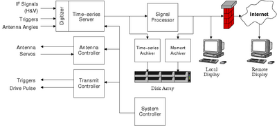
Most of CHILL's components communicate with each other using a common Gigabit Ethernet network. As a result, inexpensive, off the shelf hardware is used to interconnect the subsystems. A system-level block diagram shown in the figure illustrates this principle.

CSU-CHILL's salient features are described in below
| Antenna | |
|---|---|
| Shape | Parabolic |
| Diameter | 8.5 m |
| Feed Type | Scalar |
| Gain | 43 dBi, including feed loss |
| Beamwidth | 1.1° |
| Maximum Sidelobe | -27 dB (in any φ plane) |
| Inter-channel Isolation | -45 dB (limited by orthomode transducer) |
| ICPR | -34 dB (two-way) |
| Scan types | PPI (optional sector scan), RHI, fixed-pointing, vertically pointing |
| Max. slew rate | 18 °/sec |
| Transmitters | |
| Architecture | Coherent MOPA, STALO and COHO are GPS stabilized |
| Wavelength | 11.01 cm (2.725 GHz) |
| Peak Power | 800 kW (per channel) |
| Final PA Type | Klystron (Varian VA-87B/C) |
| PRT Range | 800 μs - 12000 μs |
| Polarization | Horizontal, Vertical, Alternating, Slant 45/135, Left/Right Circular |
| Waveform | Programmable, intra- and inter-pulse modulation supported |
| Receivers/Signal processing | |
| Sensitivity | |
| Noise Figure | ~3.4 dB |
| Noise Power | |
| Dynamic Range | 80 dB |
| Bandwidth | Programmable. Simultaneous 1 MHz and 5 MHz channels are available. |
| Range Resolution | Min: 30m, Typ: 150m programmable. |
| Max. Range Gates | ~6000 |
| Clutter Suppression | Selectable Chebyshev/Elliptic notch filter, Spectral filters under development |
| Processing modes | Pulse Pair, Spectral (under development) |
| Available data | Time-series (I/Q samples), polarimetric variables including KDP, available in real-time and archived data |
| Data Formats | Binary time-series files (with associated calibration info), Internal archive format, UF (Universal Format), netCDF (under development) |
Transmitters
Main article: CHILL Transmitters
The transmitters are a high-power Klystron based MOPA (Master-Oscillator Power Amplifier) type, whose input signals are ultimately derived from a GPS source for easy synchronization against another radar for bistatic operations. The GPS source also provides a high-stability frequency reference, corrected for drifts.
The transmitter is driven with a modulated drive pulse, which is generated by a custom-designed arbitrary waveform generator (AWG). The AWG is capable of generating a modulated waveform at a programmable IF, with a waveform table that can be downloaded from a host computer. Waveforms can change on a pulse-by-pulse basis, offering inter-pulse waveform modulation. The waveform can also be modulated within a pulse to perform pulse-compression effects, although the maximum pulse width is limited by the transmitter power supply.
A more detailed description of the CHILL transmitters and waveform generators is found in the Transmitter page.
Antenna

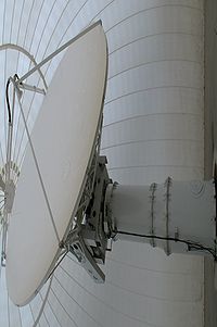
The CSU-CHILL antenna is an 8.5m diameter prime-fed parabolic reflector type. It is capable of producing a 1.1° beam, and has an antenna gain of 43 dBi (including the loss in the waveguide runs between the duplexer and the antenna). The antenna has an orthomode transducer (OMT) placed at the prime focus of the reflector, which can transmit signals in a variety of polarizations by adjusting the power and phase at the H and V ports. The antenna is positioned using a PLC which controls pairs of servo motors on each axis. The PLC is accessible through the same gigabit LAN interconnecting other parts of the radar system, and receives antenna positioning commands from the system controller.
The antenna is capable of executing a variety of scans, including azimuth (PPI), azimuth sector, elevation (RHI) and fixed-pointing scans. The elevation range includes 90°, allowing the antenna to make vertically-pointing measurements.
The antenna is mounted within an inflatable radome, which protects it from the elements, and also isolates it from wind-loading effects.
Receiver
Main article: CHILL Receivers
The CHILL receiver is a dual-channel coherent-on-transmit type, with a total of four channels. Two channels are connected to a transmitter sampling port, while the other two are connected to the LNAs. The digitized data has headers applied to it, indicating antenna position, timestamp, etc. The receivers have good dynamic range (about 80 dB) and cross-polar isolation (limited by the antenna/OMT to 45 dB).
Signal processing system
Main article: CHILL Signal Processor
The digitized radar data is processed using software developed in-house, on general purpose PC hardware. The data is subsequently archived in one of a variety of formats. Data is available as raw time-series (corresponding to NWS level-0 data), as raw covariances and as processed meteorological moments (corresponding to NWS level-1). All standard meteorological moments are available, as indicated below. In addition, polarimetric moments are available when the radar transmits in one of it's dual-polarized modes, as listed in the table.
| Symbol | Field Name | Units |
|---|---|---|
| Z | Reflectivity | dBZ |
| V | Velocity | m/s |
| W | Spectral Width | m/s |
| NCP | Normalized Coherent Power (also called Signal Quality Index or SQI) | (dimensionless) |
| Symbol | Field Name | Units |
|---|---|---|
| Zdr | Differential Reflectivity | dB |
| LDR | Linear Depolarization Ratio | dB |
| ψdp | Differential Phase Shift | degrees |
| ρHV | Copolar Correlation Coefficient | (dimensionless) |
| KDP | Specific Differential Phase | degrees/km |
Data from the signal processors are available in real-time both for further processing as well as for viewing at either a local workstation or a remote machine through an Internet connection. A platform-independent radar data viewer, VCHILL, may be used to either browse through archived data or to view real-time data as it arrives from the radar. Other alternatives include a Linux-based display program (gtk_display), which is downloadable from the CHILL CVS.
The software runs on the Linux operating system, for improved reliability and to conform to standard networking protocols. All components communicate with each other through a gigabit Ethernet network. Multiple processing algorithms may be applied simultaneously to the data by running the software on several different computers. Additional processing capabilities may be added to the system by modifying the existing software. To make this easier, the software is written in the C language, and currently does not make use of any specialized libraries which imply steep learning curves. All the software is readily available for inspection through the CVS version control system. A browsable verion has been made available.
Data archival
Currently, the radar data is archived in a customized internal format, which is described in the Data Archival page. A version of the data archiver which can write out netCDF files is currently under development.