CHILL Transmitters
This is a description of the waveform synthesis units, frequency references and transmitters used by the CSU-CHILL radar.
Frequency Source
The primary frequency reference used by CHILL is a Meridian precision GPS reference manufactured by EndRun Technologies. The reference is configured with the low phase-noise OCXO option for the best possible spectral purity. This is important since all other frequency sources are referred to this oscillator, and will affect the overall phase stability of the radar. The GPS reference generates a 10 MHz sinewave, which is then used to generate the 40 MHz clock frequencies for the waveform synthesizer and digitizer, and also to phase-lock the STALO and test signal (BITE pulse) generator.
CHILL Frequency Synthesis
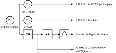
The STALO is generated by an HP8672A YIG oscillator. It is phase-locked to the 10 MHz GPS reference to maintain frequency stability and coherence with other radars which operate at the same frequency and use a GPS reference. The output of the STALO is connected to the mixers in the upconvert chain and both sets of receiver downconverters (both main channel and transmitter sample channel).
The BITE (Built-in Test Equipment) pulse is also phase-locked to the GPS. This ensures that the injected test pulse has a fixed phase relationship to the STALO, and can be used to test the Doppler (velocity) measurement capability and clutter rejection capability of the receiver in addition to power calibrations. The BITE pulse is synthesized by an HP8673H signal generator, whose output frequency and power may be digitally controlled over an HP-IB bus. The HP-IB bus at CHILL is connected through a serial port to the HP-IB server, which allows the system controller to set the BITE pulse parameters.
The 40 MHz digitizer clock is generated by multiplying the 10 MHz reference by 4. A high-performace Wenzel Associates low-phase-noise device is used for this purpose. This clock is also used by the digital modulator control logic. The DACs on the digital modulator, however, run at a 160 MHz clock rate, which is generated by further multiplying the 40 MHz output by four to generate a 160 MHz clock.
Waveform Generator
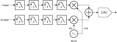
The waveform generator produces a modulated IF pulse, which is then upconverted to S-band. The modulation is performed digitally using TI DAC5686 Digital Upconverter (DUC) chips. These devices accept a stream of I/Q pairs at 10 MHz, these are interpolated using a cascade of 2x interpolators up to 160 MHz. They are then quadrature modulated with a signal generated from a numerically controlled oscillator (or NCO), and converted to analog using a DAC. The NCO frequency is set to 50 MHz, the IF Frequency for CHILL.
There are two DUCs in the waveform generator, one for each polarization channel. The upconverters are interfaced to a controller FPGA, which downloads a sequence of I/Q values stored in a bank of memory. The sequence is programmable from a host computer. The controller FPGA is also responsible for generating the trigger signals for the transmitter power supplies, digitizers and BITE. The upconverter is carefully designed to prevent noise from the digital control logic from interfering with the sensitive analog IF signals. Control signals from the FPGA, in the form of differential TTL (RS-422) signals, are routed to various points within the radar system. Several additional I/Os are available for expansion and interfacing to customized hardware.
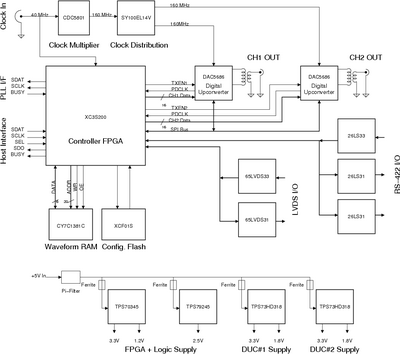
The Digital upconverter board is connected to an embedded controller based on an ARM CPU from Technologic Systems. The controller runs a control server, which accepts parameters from the system controller over the network and downloads these to the DUC board. In this manner, complete operation of the transmitter can be controlled from the system controller. Standard triggering modes available are listed in the table below. Additional triggering modes, polarization sequences, etc. can be programmed into the controller, should the need arise. A sequence of up to 256 points may be generated, according to project needs. It should be noted, however, that due to the nature of the transmitter high-voltage supplies, not all modes offer optimal performance.
| Sequence | Description |
|---|---|
| V | V-only mode |
| H | H-only mode |
| VH | Alternating (V-H-V-H) mode |
| VHS | Simultaneous mode |
| Hybrid | First half of integration cycle is same as VH, second half is same as VHS |
| Staggered PRT | Available in V, H, VH and VHS modes where alternate pulses switch between one of two PRTs |
The drive pulse for the klystrons can be shaped with any arbitrary envelope using the digital modulators. Shaping of the transmitter pulse allows it's bandwidth to be precisely adjusted. In addition, modulation within the pulse as well as between pulses may be applied.
Upconversion Chain
The output of the DUCs contains unwanted spurious signals as a result of the DDS process used by the NCO. These are filtered out using a bandpass filter. The filtered IF (at 50 MHz) is then upconverted to S-band by mixing with the STALO frequency at 2.775 GHz and filtering the lower sideband at 2.725 GHz with a bandpass filter. The upconverted pulse is then gated using a GaAs high-speed switch. These switches are enabled only during the shaped pulse output from the DUCs, preventing any noise from the upconverters from entering other parts of the system, particularly the receivers.
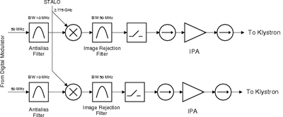
After passing through isolators, the pulsed signals are amplified through the solid-state Initial Power Amplifiers (IPAs) manufactured by Stealth Microwave. They are then passed on to the Klystron PAs through another pair of isolators, to protect the IPAs from damage in case of high reflected power.
Transmitters
The transmitters used at CHILL were originally designed for the AN/FPS-18 Air Surveillance radar set. They make use of a Varian VA-87B/C Klystron coupled to a resonant-line type high-voltage power supply. The power supply produces a high-voltage pulse of approximately 80-100 kV in response to a trigger pulse generated by the digital upconverter board FPGA. The high voltage pulse is used as the beam voltage for the Klystron's cathode. By carefully timing the high-voltage trigger pulse, the cathode pulse and RF drive signal are lined up, causing the Klystron to amplify the drive signal to the final RF output level. At the output of the Klystron, a 50 dB directional coupler obtains a sample of the transmit pulse, which goes to the transmitter sample channel of the receivers. The circulator protects the delicate receivers during the transmit pulse. The turnstile waveguide switch allows injection of test signals into the receiver. Another directional coupler forms the reference plane of the radar, where the transmit power is measured and also a test signal may be injected. The second turnstile switch allows the transmitter output to be switched between the antenna and a dummy load.
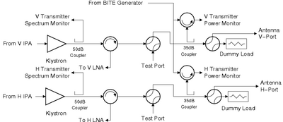
The turnstile switches in the figure are shown in their normal operating condition. The first set of switches can be moved to the test position after the transmitters are switched off to access the test point. A typical use for this mode is to inject broadband noise from a noise diode. This gets coupled to the LNAs, which allows their noise figure to be calculated (including the insertion loss of the circulator and receiver protection tubes). The second set of switches are used when performing hot/cold load tests with the antenna pointing at clear sky as a cold load and the dummy load as a hot load.
The transmitter output power is measured through a 35 dB directional coupler and a low-power circulator. By making simultaneous measurements of both transmitters' output power, the effects of transmitter drift on differential measurements such as ZDR are eliminated. These measurements are made once every two seconds, and are embedded into the data stream generated by the signal processor.
The BITE pulse is injected into the same 35 dB coupler through the circulator. This pulse is generated at a known offset from the transmitter, and can be used to measure the receiver drift in order to compensate for the same when making differential measurements. The BITE signal is also used to periodically measure the receiver gain by injecting a known power level. As a result of using the same coupler both for transmitter monitoring as well as receiver gain calibration, this point is used as the reference plane for all calibrations of the radar.