Uploads by Dabrunkow
From CSU-CHILL
This special page shows all uploaded files.
| Date | Name | Thumbnail | Size | Description | Versions |
|---|---|---|---|---|---|
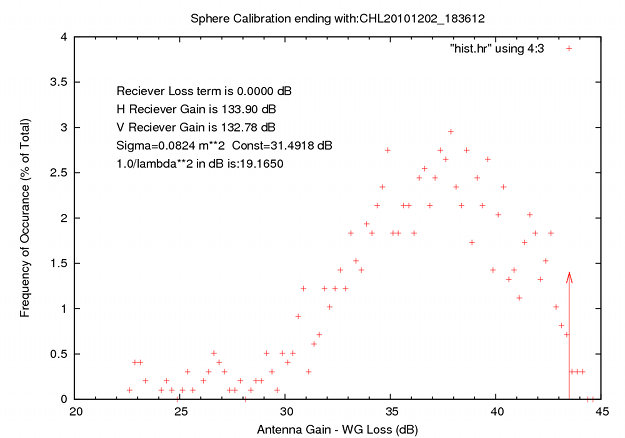
| 10:49, 1 January 2011 | Sphcal02dec2010.png (file) |  |
55 KB | sphere cal histogram 02dec2010 | 3 |
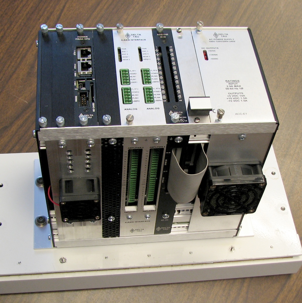
| 14:44, 29 December 2009 | Ppmac.jpg (file) |  |
495 KB | Chill Power PMAC rack | 1 |
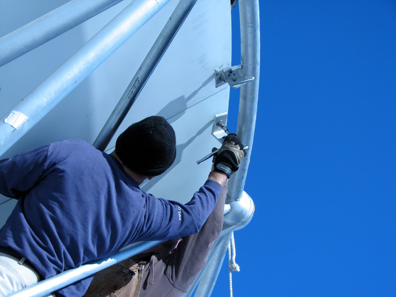
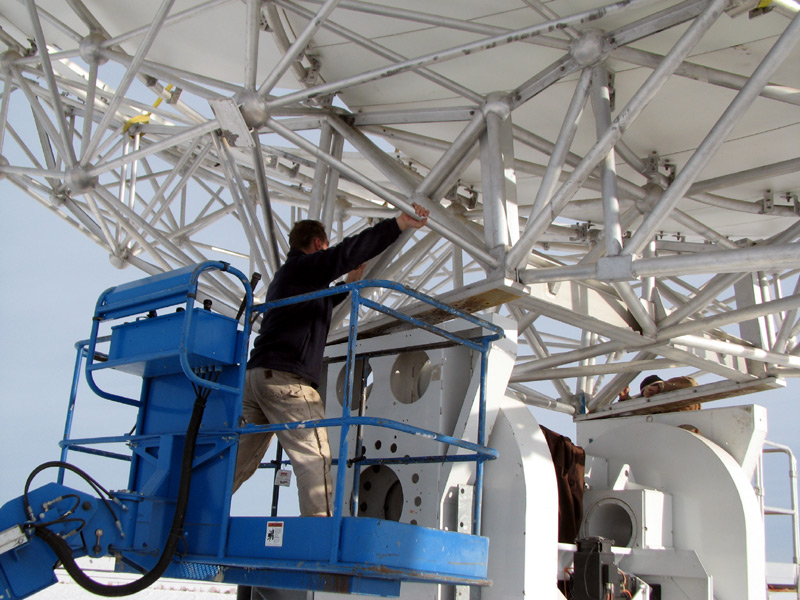
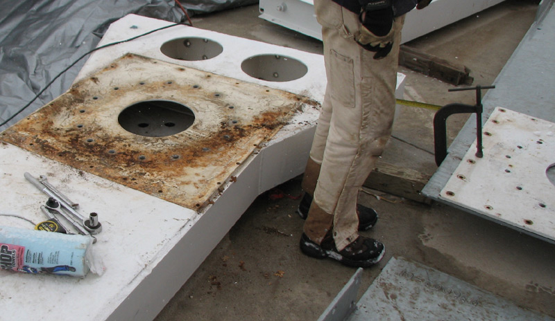
| 15:30, 2 January 2008 | Replace-panels.jpg (file) |  |
109 KB | Panels are bolted in from the rear face. | 1 |
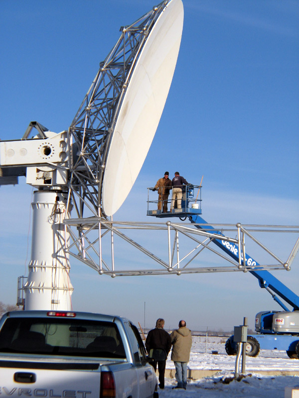
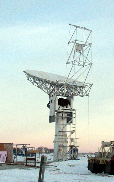
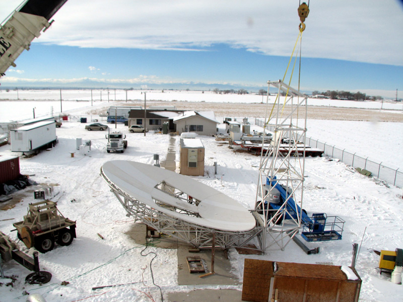
| 15:30, 2 January 2008 | Step1-complete2.jpg (file) |  |
146 KB | Antenna in near zero degree elevation position. | 1 |
| 15:29, 2 January 2008 | Step1-complete.jpg (file) |  |
140 KB | Completion of first stage of antenna assembly. | 1 |
| 15:28, 2 January 2008 | Dish-install2.jpg (file) |  |
169 KB | Dish is bolted to sidearms. | 1 |
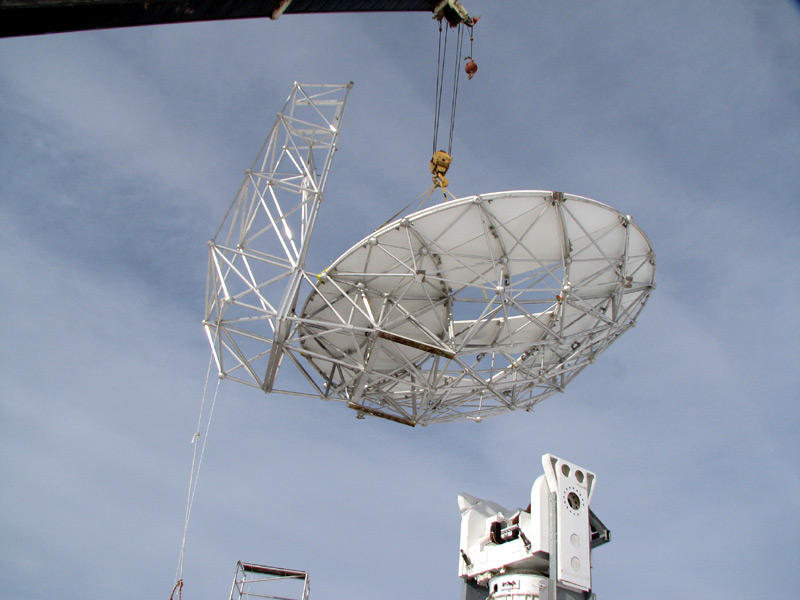
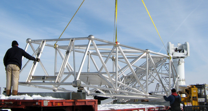
| 15:27, 2 January 2008 | Dish-install1.jpg (file) |  |
102 KB | Nearly complete antenna is lifted into place. | 1 |
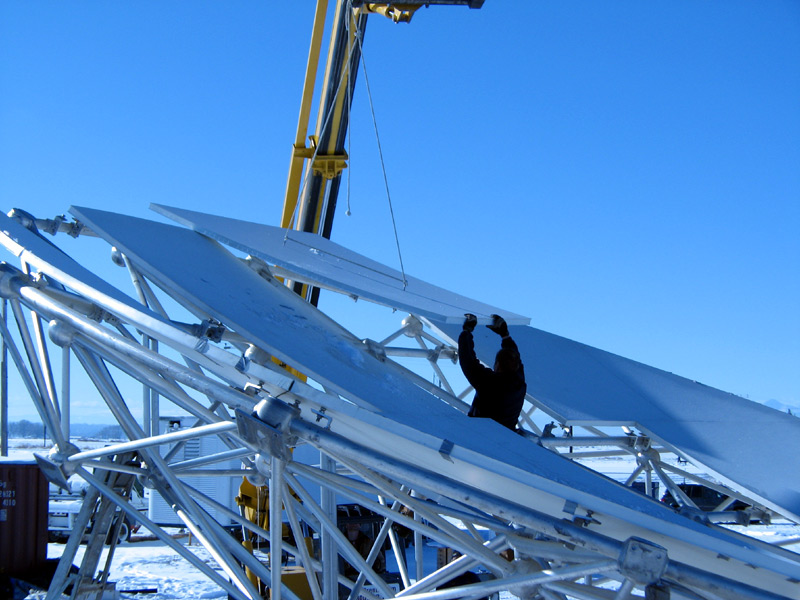
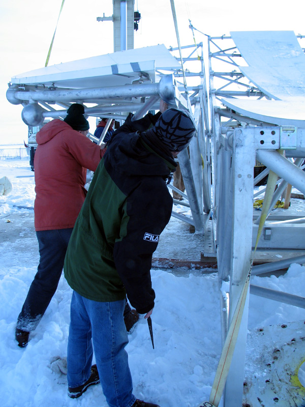
| 15:27, 2 January 2008 | Replace-panels2.jpg (file) |  |
142 KB | Replacing panels into backup structure. | 1 |
| 15:26, 2 January 2008 | Install-boom.jpg (file) |  |
164 KB | The feed boom is lifted into place and bolted to the antenna. | 1 |
| 15:25, 2 January 2008 | Assemble-pieces2.jpg (file) |  |
157 KB | The two side reflector pieces are bolted to the center dish section. | 1 |
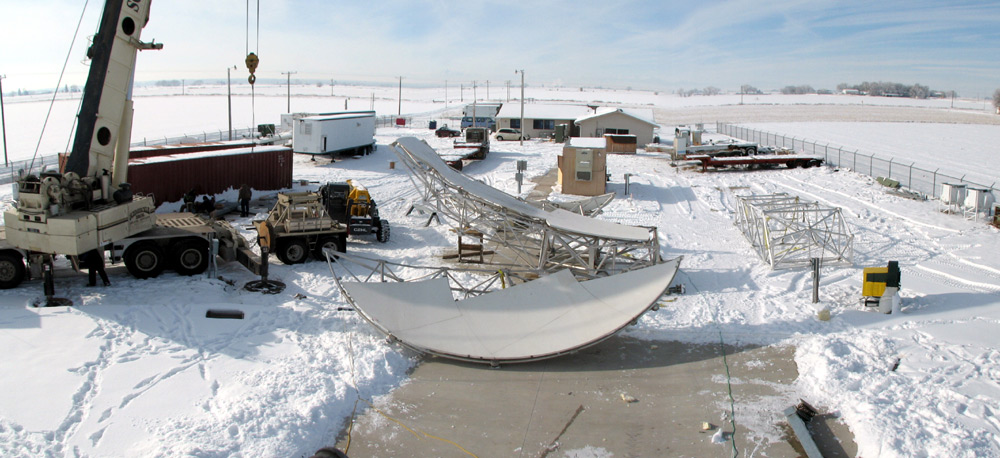
| 15:24, 2 January 2008 | Assembly-overview1.jpg (file) |  |
165 KB | The major antenna pieces on the ground awaiting assembly. | 1 |
| 15:22, 2 January 2008 | Moving-boom.jpg (file) |  |
111 KB | The feed-boom is lifted off the trailer. | 1 |
| 15:21, 2 January 2008 | Finished-counterweight.jpg (file) |  |
133 KB | The modified counterweight is now on the pedestal and the cross-member connecting the two sidearms has been mounted. | 1 |
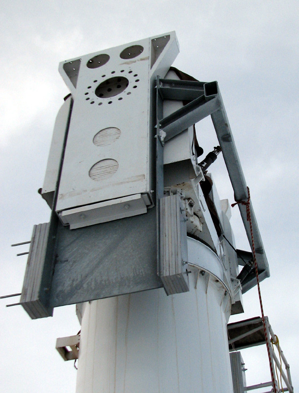
| 15:19, 2 January 2008 | Sidearm-mod.jpg (file) |  |
185 KB | Sidearm extension structure is now bolted onto the original sidearm. | 1 |
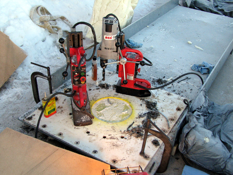
| 15:16, 2 January 2008 | Hole-transfer.jpg (file) | 196 KB | Old mounting plate is used as a template for drilling holes in the new sidearm extension. | 1 | |
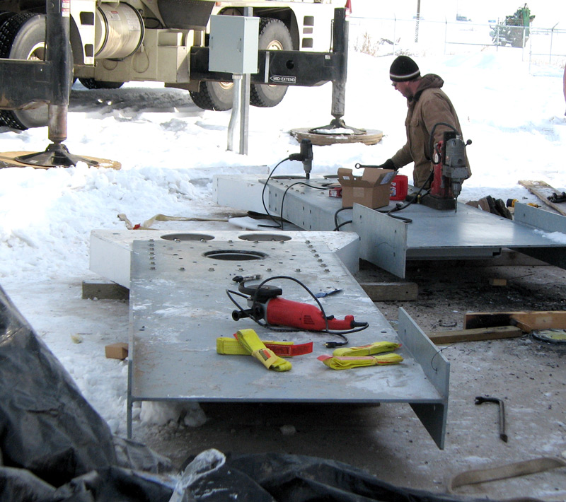
| 15:15, 2 January 2008 | Mounting-plate.jpg (file) |  |
119 KB | View of the transfer of mounting holes from the original 3' square plate to the new sidearm extnsions. | 1 |
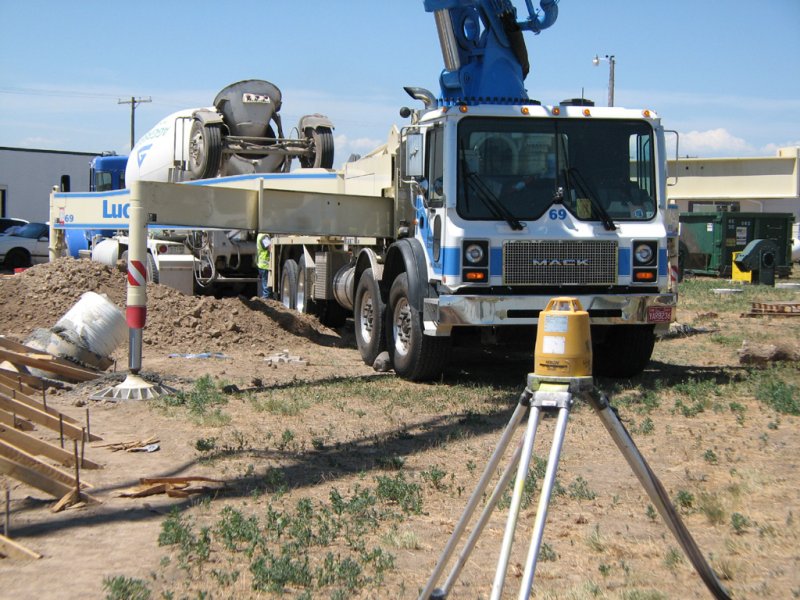
| 16:37, 9 July 2007 | Leveler-pumper.jpg (file) |  |
123 KB | View of laser leveler source with concrete pump in background. | 1 |
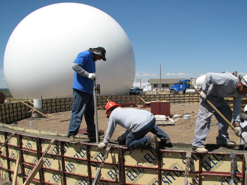
| 16:37, 9 July 2007 | Ring-finishing.jpg (file) |  |
107 KB | Leveling and finishing process on radome ring foundation. | 1 |
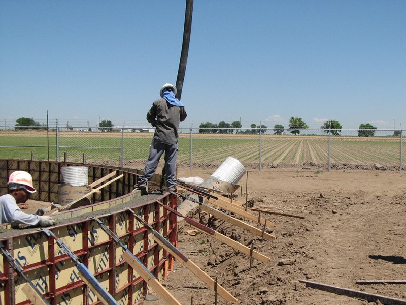
| 16:36, 9 July 2007 | Pumping.jpg (file) |  |
117 KB | Filling the radome foundation forms with remote controlled concrete pump. | 1 |
| 16:35, 9 July 2007 | Pour07a.jpg (file) |  |
69 KB | Looking to the southwest with new foundation forms in foreground and old radome in background. | 1 |
| 16:34, 9 July 2007 | Ped-rebar.jpg (file) |  |
145 KB | Antenna pedestal foundation reinforcement before the concrete pour. | 1 |
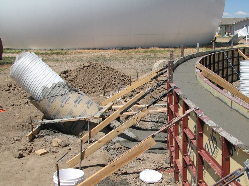
| 16:33, 9 July 2007 | Inflation-duct.jpg (file) |  |
131 KB | One of three inflation ducts as seen before backfilling the radome foundation. | 1 |
| 16:30, 9 July 2007 | Overview2.jpg (file) |  |
76 KB | Looking to the southwest with new foundation forms in forground and old radome in background. | 1 |
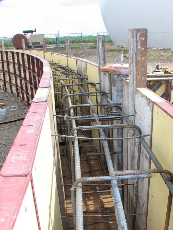
| 16:28, 9 July 2007 | Ring-rebar.jpg (file) |  |
112 KB | Radome ring reinforcement before pour. | 1 |
| 16:27, 9 July 2007 | Overview.jpg (file) |  |
100 KB | View to the southeast showing new radome ring forms. | 1 |