X-band Solid State Transmitter Monitor User's Guide (TN-008)
This article describes the transmitter monitor board developed at CSU-CHILL. This board is designed for use in the Solid-state X-band project (WiBEX). The board monitors the operating conditions of the solid-state transmitter, and reports these to a higher-level controller. It can also shut down the transmitter in the event of a fault. The board is fully programmable via a Modbus/RTU interface.
Introduction
The transmitter monitor board is a critical component in the WiBEX radar design. Its primary task is to monitor the operating conditions of the solid-state transmitter. Secondary functions include a split power supply (+/- 5V) for the X-band microwave switches used in the front end of the WiBEX radar, a Peltier cooler driver for the X-band LNAs and a microwave switch driver.
Block Diagram
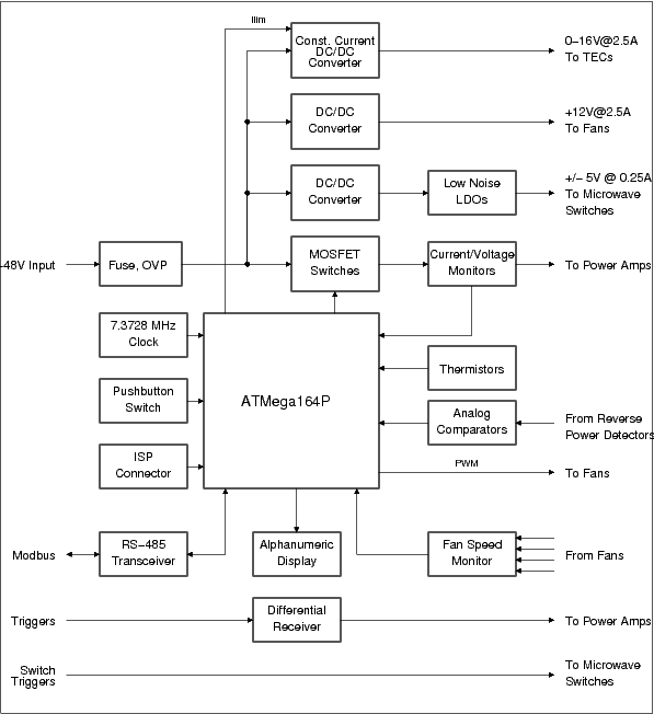
The figure below shows a block diagram of the board. The primary controller on the board is an Atmel ATMega164P microcontroller. This controller implements the main logic of the board, along with the Modbus/RTU slave logic. Various peripherals available on the microcontroller are used to interface to the analog electronics on the board.
Block Diagram
Components
Power Entry
Microcontroller
RS-485 Interface
Alphanumeric Display
Power Amplifier Supply
MOSFET Switch
Voltage Monitor
Current Monitor
Microwave Switch Supply
DC/DC Converters
LDOs
Fan Power Supply
TEC Power Supply
Thermistors
Fan Monitor
Modbus Registers
The interface to the synthesizer is through Modbus/RTU. The Modbus communications model is a single master controlling various slave devices[1]. Each slave is addressable, and has different registers which may be read or written. This design implements read-only registers (referred to as Input Registers in the Modbus specifications) and read-write registers (Holding Registers). There are no coils or status bits available.
Input Registers
The available input registers are shown in the table below:
| Register Number | Name | Description |
|---|---|---|
| 1000 | ALARM | Indicates the cause of any alarms indicated by the Modbus ALM signal. Reading the register clears the alarm condition and deasserts the Modbus ALM signal. |
| 1001 | STATUS | Indicates the operating status of the transmitter. |
| 1002 | TEMP_AMP1 | Amplifier 1 temperature, in degrees C multiplied by 100. |
| 1003 | TEMP_AMP2 | Amplifier 2 temperature, in degrees C multiplied by 100. |
| 1004 | FAN1_RPM | Fan 1 speed, in revolutions per minute. |
| 1005 | FAN2_RPM | Fan 2 speed, in revolutions per minute. |
| 1006 | FAN3_RPM | Fan 3 speed, in revolutions per minute. |
| 1007 | FAN4_RPM | Fan 4 speed, in revolutions per minute. |
| 1008 | V_AMP1 | Amplifier 1 voltage, in millivolts. |
| 1009 | I_AMP1 | Amplifier 1 current, in milliamperes multiplied by 10. |
| 1010 | V_AMP1 | Amplifier 2 voltage, in millivolts. |
| 1011 | I_AMP1 | Amplifier 2 current, in milliamperes multiplied by 10. |
| 1012 | TEMP_HOT | Peltier cooler hot-side (heatsink) temperature, in degrees centigrade multiplied by 100. |
| 1013 | TEMP_COLD | Peltier cooler cold-side (LNA) temperature, in degrees centigrade multiplied by 100. |
| 1014 | PFAN_RPM | Peltier cooler heatsink fan speed, in revolutions per minute. |
| 1015 | RP_COUNT | Reverse power pulses per second. |
Input Register Map
Holding Registers
The available holding registers are shown in the table below:
| Register Number | Name | Description |
|---|---|---|
| 1000 | DISP_MODE | Mode of the alphanumeric display. |
| 1001 | PA_CONTROL | Power amplifier power control. |
| 1002 | FAN_MODE | Power amplifier cooling fan mode. |
| 1003 | FAN_TGTSPEED | Target speed of the power amplifier cooling fans when in manual mode. |
| 1004 | FAN_P_FACTOR | Proportional gain for the fan speed control loop, when in automatic mode. |
| 1005 | FAN_I_FACTOR | Integral gain for the fan speed control loop, when in automatic mode. |
| 1006 | FAN_D_FACTOR | Differential gain for the fan speed control loop, when in automatic mode. |
| 1007 | RP_COUNT_LIMIT | Number of reverse power pulses per second needed to trigger an alarm. |
| 1008 | PELTIER_TEMP_SETPOINT | Temperature that the Peliter cooler tries to attain, when in closed loop (automatic) mode. |
| 1009 | PELTIER_P_FACTOR | Proportional gain for the Peltier cooler control loop, when in automatic mode. |
| 1010 | PELTIER_I_FACTOR | Integral gain for the Peltier cooler control loop, when in automatic mode. |
| 1011 | PELTIER_D_FACTOR | Differential gain for the Peltier cooler control loop, when in automatic mode. |
| 1012 | PA_VOLT_LOW | Lower limit of the acceptable power supply input voltage range. |
| 1013 | PA_VOLT_HIGH | Higher limit of the acceptable power supply input voltage range. |
| 1014 | PA_CURRENT_HIGH | Upper limit of the current that may be drawn at the power amplifier contacts. |
| 1015 | PA_TEMP_HIGH | Maximum power amplifier temperature. |
| 1016 | PELTIER_TEMP_HIGH | Maximum Peltier hot-side temperature. |
| 1017 | FAN_SPEED_LOW | Minimum rotation speed before a fan failure is declared. |
Holding Register Map
Connectors
Other Resources
References
- ↑ http://www.modbus.org/specs.php Modbus specifications
