High Rain Rates at Denver International Airport Observed with Indexed Beams: Difference between revisions
Pat kennedy (talk | contribs) No edit summary |
m (→Time-lapse) |
||
| (27 intermediate revisions by 2 users not shown) | |||
| Line 1: | Line 1: | ||
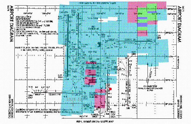
On 10 September 2006, the CSU-CHILL radar made continuous 0.5 deg | On 10 September 2006, the CSU-CHILL radar made continuous 0.5° elevation PPI scans in alternating VH polarization mode. In these scans, the beam revisited a given location at essentially one minute intervals. While this scanning procedure was in use, heavy thunderstorm precipitation developed around Denver International Airport. To provide geographic references for the radar data, the FAA airport taxi diagram for KDEN is shown below. A red dot has been added to indicate the approximate location of the ASOS sensors | ||
elevation PPI scans in alternating VH polarization mode. In these scans, | where the basic elements of the surface weather reports (METARS) are measured. A horizontal size scale can be obtained from the runway length depictions; runway 35L / 17R (immediately to the west of the ASOS dot) is 3.66 km (12,000 ft) long.) | ||
the beam revisited a given location at essentially one minute | |||
intervals. While this scanning procedure was in use, heavy | |||
thunderstorm precipitation developed around Denver International | |||
Airport. To provide geographic references for the radar data, | |||
the FAA airport taxi diagram for KDEN is shown below. A red dot | |||
has been added to indicate the approximate location of the ASOS sensors | |||
where the basic elements of the surface weather reports (METARS)are measured. | |||
A horizontal size scale can be obtained from the runway length depictions; | |||
runway 35L / 17R (immediately to the | |||
(12,000 ft) long. | |||
For each PPI scan, the one-way specific propagation differential phase ( | [[Image:KDEN_taxi_chart.png|650px]] | ||
in degrees per km) was calculated using the methods | |||
For each PPI scan, the one-way specific propagation differential phase (<math>K_{dp}</math> in degrees per km) was calculated using the methods in <ref name="cifelli">[http://www.agu.org/journals/jd/jd0218/2000JD000264/ Cifelli et. al, ''J. Geophys. Res., 2002'']</ref>. <math>K_{dp}</math>-based rain rates were then provided by <math>R = 40.5 * K_{dp} ^{0.85}</math>, from Eq 8.14 in <ref name="bc">Bringi and Chandrasekar, ''Polarimetric Doppler Weather Radar: Principles and Applications'', (2001)</ref>. | |||
R = | |||
In the time lapse sequence shown below, these rain rates have been color | In the time lapse sequence shown below, these rain rates have been color | ||
coded as follows: | coded as follows: | ||
<center> | |||
< | {| {{Prettytable}} | ||
!{{Hl3}} | Rain Rate<br>(mm/hr) | |||
!{{Hl3}} | Color Codes | |||
|- | |||
|25 | |||
|light blue | |||
|- | |||
< | |50 | ||
|light red | |||
|- | |||
|75 | |||
|green | |||
|- | |||
|100 | |||
|blue | |||
|- | |||
|125 | |||
|yellow | |||
|- | |||
|150 | |||
|dark red | |||
|- | |||
|175 | |||
|grey | |||
|} | |||
</center> | |||
(Note: PPI times (UTC) appear in the lower left quadrant of each image). | |||
232832.gif | |||
===Time-lapse=== | |||
<center> | |||
<imgloop delay=1000 imgprefix="http://www.chill.colostate.edu/anim/20061110_KDEN_KDP/" width=650 height=423> | |||
232832.gif|232832 UTC | |||
232932.gif|232932 UTC | |||
233032.gif|233032 UTC | |||
233132.gif|233132 UTC | |||
233231.gif|233231 UTC | |||
233330.gif|233330 UTC | |||
233430.gif|233430 UTC | |||
233529.gif|233529 UTC | |||
233629.gif|233629 UTC | |||
233729.gif|233729 UTC | |||
233828.gif|233828 UTC | |||
233928.gif|233928 UTC | |||
234027.gif|234027 UTC | |||
234127.gif|234127 UTC | |||
234227.gif|234227 UTC | |||
234327.gif|234327 UTC | |||
234426.gif|234426 UTC | |||
234525.gif|234525 UTC | |||
234625.gif|234625 UTC | |||
234724.gif|234724 UTC | |||
234824.gif|234824 UTC | |||
234924.gif|234924 UTC | |||
235023.gif|235023 UTC | |||
235123.gif|235123 UTC | |||
235222.gif|235222 UTC | |||
235322.gif|235322 UTC | |||
</imgloop> | |||
</center> | |||
The patterns evident in the time lapse sequence demonstrate the small time and space scales on which thunderstorm precipitation evolves. The METAR prevailing visibility decreased to 0.25 statute miles in heavy rain at 2342 UTC. The CSU-CHILL data indicate that even higher rain rates existed over runway 35R - 17L, while rainfall rates never reached 25 mm per hour over the approach end of runway 7 in the western portion of the airport. Since the radar data were collected in indexed beam mode, the range gate azimuths remained constant. These indexed beams improve the frame-to-frame stability in the time lapse sequence. | |||
==References== | |||
<references/> | |||
[[Category:Featured Articles]] | |||
Latest revision as of 15:15, 29 April 2008
On 10 September 2006, the CSU-CHILL radar made continuous 0.5° elevation PPI scans in alternating VH polarization mode. In these scans, the beam revisited a given location at essentially one minute intervals. While this scanning procedure was in use, heavy thunderstorm precipitation developed around Denver International Airport. To provide geographic references for the radar data, the FAA airport taxi diagram for KDEN is shown below. A red dot has been added to indicate the approximate location of the ASOS sensors where the basic elements of the surface weather reports (METARS) are measured. A horizontal size scale can be obtained from the runway length depictions; runway 35L / 17R (immediately to the west of the ASOS dot) is 3.66 km (12,000 ft) long.)

For each PPI scan, the one-way specific propagation differential phase ( in degrees per km) was calculated using the methods in [1]. -based rain rates were then provided by , from Eq 8.14 in [2]. In the time lapse sequence shown below, these rain rates have been color coded as follows:


| Rain Rate (mm/hr) |
Color Codes |
|---|---|
| 25 | light blue |
| 50 | light red |
| 75 | green |
| 100 | blue |
| 125 | yellow |
| 150 | dark red |
| 175 | grey |
(Note: PPI times (UTC) appear in the lower left quadrant of each image).
232832.gif
Time-lapse
|
|
||
|
The patterns evident in the time lapse sequence demonstrate the small time and space scales on which thunderstorm precipitation evolves. The METAR prevailing visibility decreased to 0.25 statute miles in heavy rain at 2342 UTC. The CSU-CHILL data indicate that even higher rain rates existed over runway 35R - 17L, while rainfall rates never reached 25 mm per hour over the approach end of runway 7 in the western portion of the airport. Since the radar data were collected in indexed beam mode, the range gate azimuths remained constant. These indexed beams improve the frame-to-frame stability in the time lapse sequence.
References
- ↑ Cifelli et. al, J. Geophys. Res., 2002
- ↑ Bringi and Chandrasekar, Polarimetric Doppler Weather Radar: Principles and Applications, (2001)