Frequency Synthesizer User's Guide (TN-006)
This article describes the Frequency Synthesizer developed at CSU-CHILL suitable for use as the STALO for the Solid-state X-band project as well as on the CSU-CHILL and CSU-Pawnee radar systems.
Block Diagram
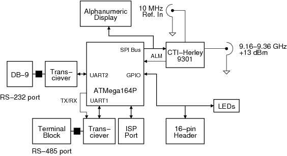
The figure below shows a block diagram of the frequency synthesizer. An Atmel microcontroller (ATmega164P) is used as the primary controller. Two serial interfaces are provided, RS-232 and RS-485. The RS-232 interface may be configured as a DCE or DTE through jumpers. An in-system programming (ISP) port is provided. Three indicator LEDs and 8 GPIOs are available. A Herley-CTI synthesizer module produces the 9 GHz output. Finally, an alphanumeric display is used to indicate the current operating frequency.
Components
Microcontroller
The microcontroller used is an Atmel ATmega164P. This device contains 16k Flash memory, 1k of SRAM and 512 bytes of EEPROM. The ATmega series of controllers is chosen since they provide an inexpensive means of controlling remote devices, and open-source programming tools such as WinAVR are available.
Two independent USARTs are available on the device. In this design, they are used to drive the RS-232 and RS-485 interfaces of the synthesizer. The RS-485 interface is used to implement the Modbus/RTU protocol. This permits the synthesizer to be remotely controlled, while sharing the control bus with various other devices that also use the Modbus protocol.
The SPI interface port available on the microcontroller provides a convenient means of controlling the Herley-CTI microwave synthesizer module, which requires a serial interface. The same interface is also used to control the on-board LED display.
I/O ports available on the controller are used to implement the 8-bit GPIO port on the board. Each bit has independent direction control and an optional pullup resistor.
Synthesizer
Bus Interface
Display
External Links
- http://www.atmel.com Atmel website
