CHILL image collection
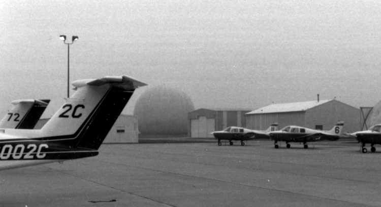
Fall 1989: The CHILL's home base site was located a short distance northeast of the parking ramp for the University of Illinois pilot training program at Willard Airport (KCMI).
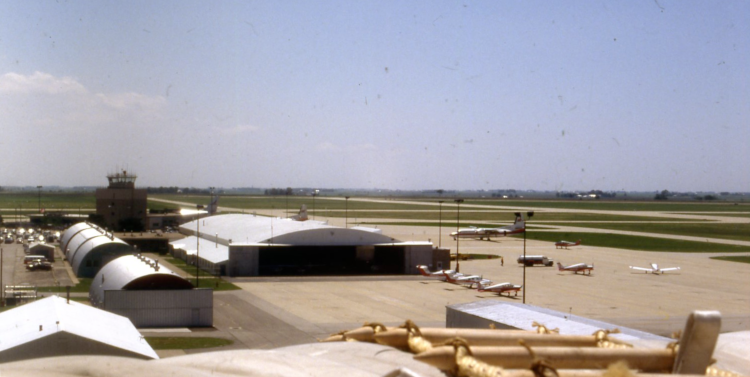
Spring 1989: View from the top of the radome looking in the opposite direction from the preceding picture (towards the southwest). The top of the dome was reached by climbing the rope ladder seen in the bottom of the picture.
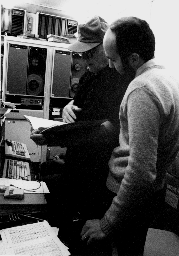
~1986 - 1987: Gene Mueller and Dave Brunkow, primary electrical engineering staff for the CHILL radar. This picture was taken in the technical operating area that was added to the rear of the FPS-18 van during the NSF-funded radar upgrade in the mid-1980's. (Photo credit: ISWS archives via Nancy Westcott and Steve Hilberg).
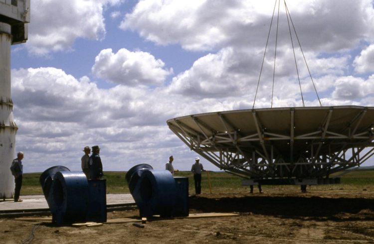
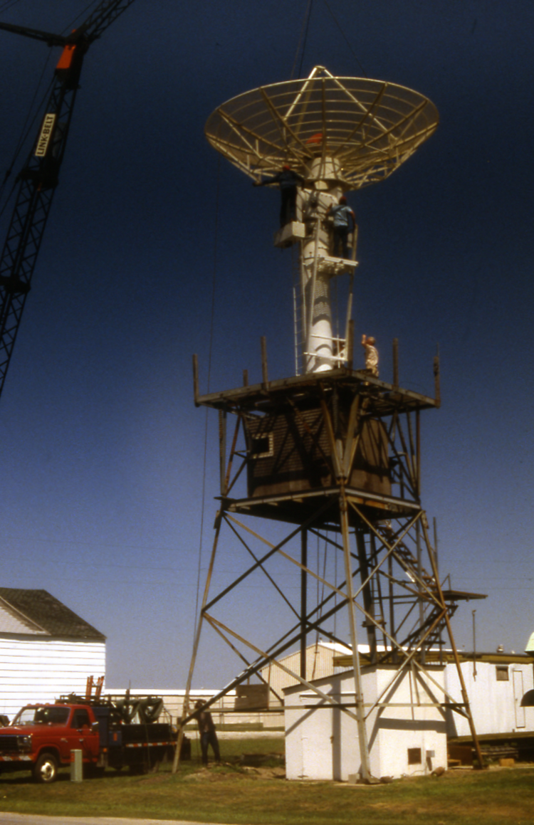
3 June 1987: Lifting the S-band reflector onto the pedestal at the Dickinson, North Dakota Municipal Airport (KDIK). The remote deployment project at Dickinson was the first utilization of the CHILL radar after its promotion to a base-funded NSF Facility.
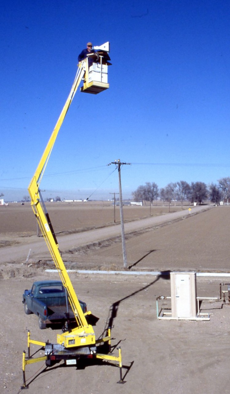
11 December 1990: To remove the feed horn support struts from the H and V polarization planes, the antenna was rotated 45 degrees when the CHILL was transferred to CSU. Pattern measurements were undertaken to evaluate the effects of the antenna rotation. For the initial pattern measurements, Gene Mueller operated a signal generator connected to a standard gain horn in a rented lift.
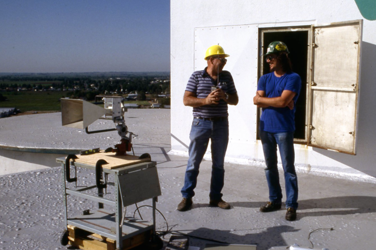
29 May 1991: The lift did not raise the signal source to a sufficient height with respect to the CHILL antenna. Subsequent pattern measurement experiments involved moving the signal generator and horn to the roof of a silo that was part of a sugar processing plant located ~3 km southwest of CHILL. In this picture CHILL technician Ken Pattison (left) is seen with Western Sugar employee Robert Schaeffer.
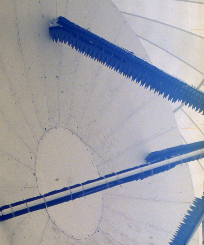
4 June 1991: Some of the pattern experiments involved applying microwave absorbing material to the feed struts. Antenna pattern sidelobe levels were not appreciably improved through the use of the absorber material.
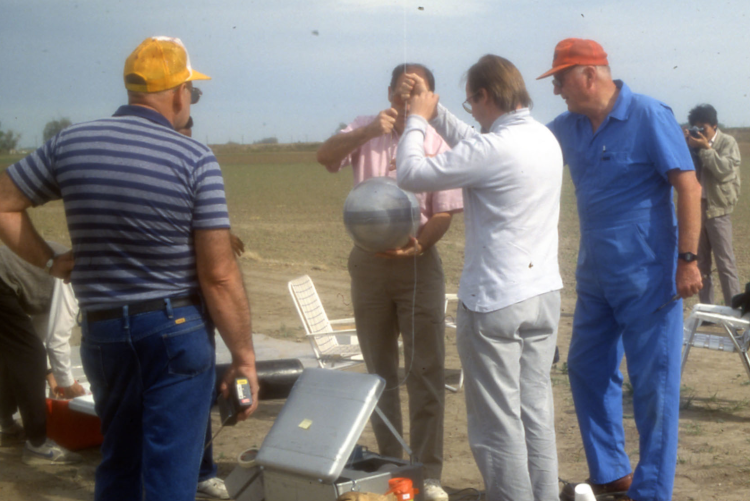
21 May 1991: In addition to pattern measurements, sphere calibrations of the radar were also done when CHILL operations began at CSU. The initial calibrations were done with the metal sphere target suspended from a tethered balloon. The sphere is being connected to the tether line in this picture. Seen from left to right are: Ken Pattison (yellow hat), Tom Mckee (mostly hidden and holding the sphere), Jon Kleist (white shirt) and Gene Mueller (red hat).
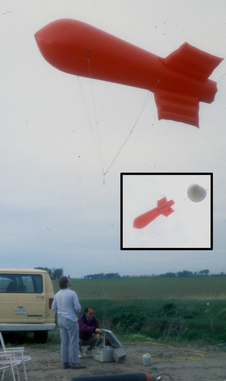
21 May 1991: Calibration sphere in flight. The tail fin-equipped balloon provides greater flight stability under breezy conditions. Tom McKee and Jon Kliest are operating the winch.
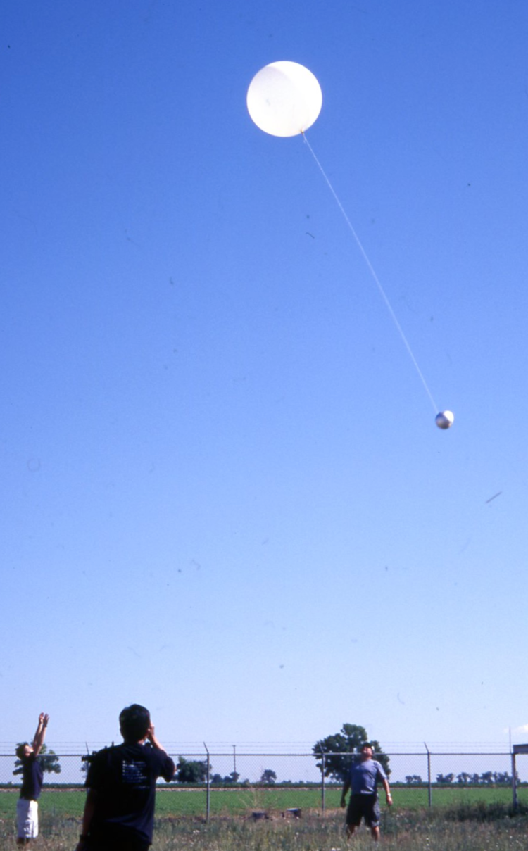
26 June 2003: Runway expansions at the Greeley Weld County airport located next to the CSU-CHILL site caused increased complications in getting FAA permission to conduct tethered balloons near the radar. This caused the transition to using free-flying balloons carrying expendable, low mass, foil covered styrofoam ball targets for the sphere calibrations. The calibration sphere flight shown here was conducted during the summer 2003 REU project.
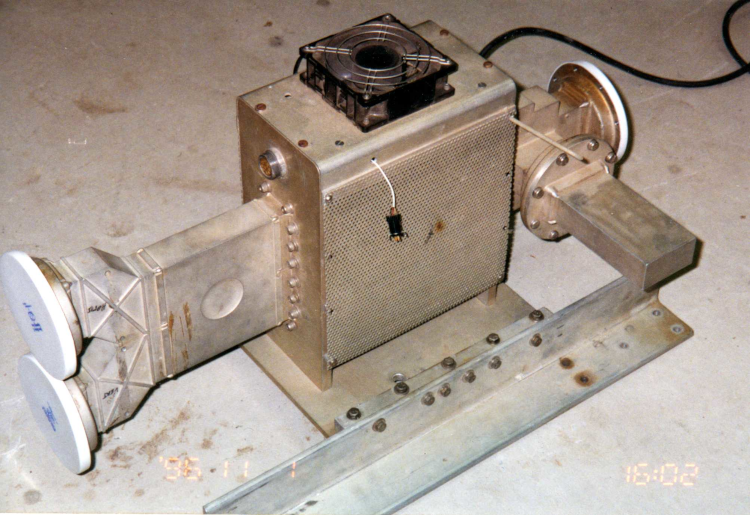
11 January 1996: The Raytheon switchable circulator was used on the CHILL radar between the summer of 1981 and late 1994. The transmitter / receiver hardware was connected to the single waveguide connection (with a white cover) on the right. In essence, reversing the sense of the magnetic field established by the ferrite material inside the switch shifted the microwave propagation path between the two waveguide connections on the left side of the switch.
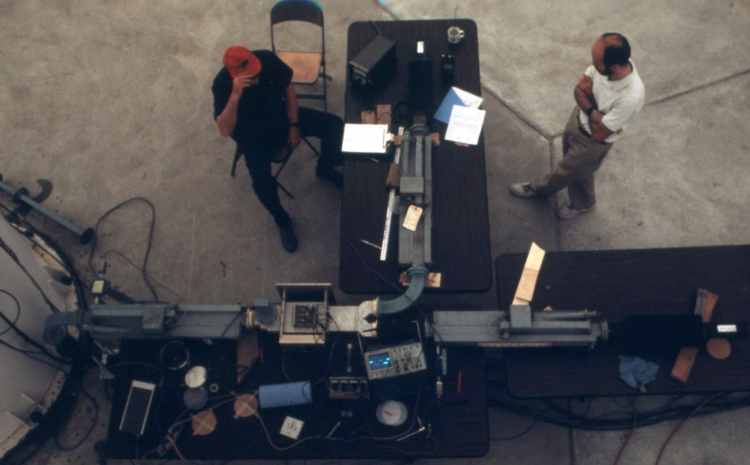
8 August 1991: The tuning of the drive pulses that changed the magnetization of the ferrite material in the Raytheon switch was critical to obtaining good polarization switch performance. This picture shows a tabletop switch test configuration that was temporarily set up on the floor of the radome. Various switch tuning procedures were tested using this arrangement; engineers from the NCAR CP-2 radar also participated in these tuning procedure tests. Gene Mueller (left) and Dave Brunkow (right) are seen in this picture.
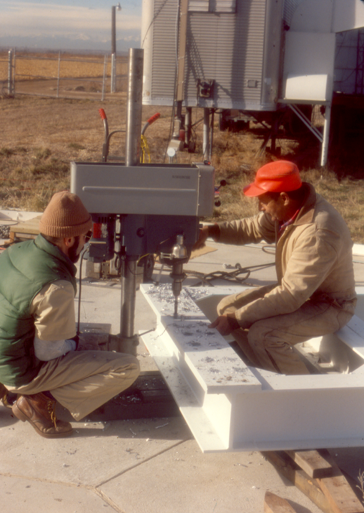
8 December 1993: The second generation center-fed CHILL antenna was delivered without the holes drilled for the bolts that connected the adaptor plate antenna base to the counter weights on the positioner. (This manufacturing decision was made due to uncertainty regarding the locations of the holes in the counter weight faces. Just prior to this picture, a crane had temporarily lifted the adaptor plate into place on the counter weight faces, allowing the existing bolt hole locations to be punch marked on the adaptor plate. In this picture, Charlie Wilkins (red hat), Atmospheric Science Department machinist, is drilling the holes for the antenna mounting bolts. Dave Brunkow (brown hat) monitors the process.
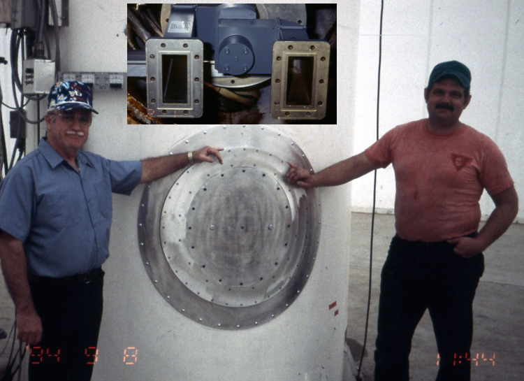
8 September 1994
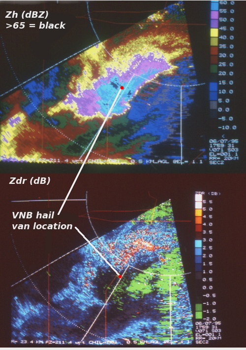
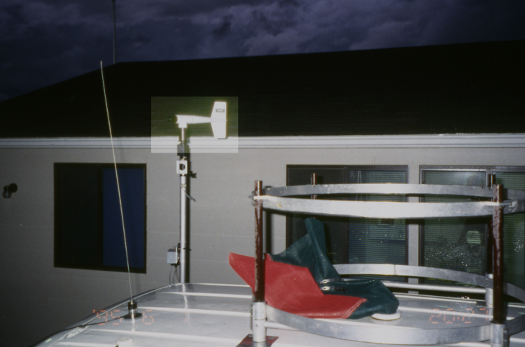
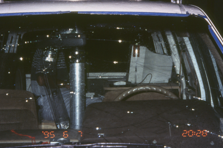
7 June 1995
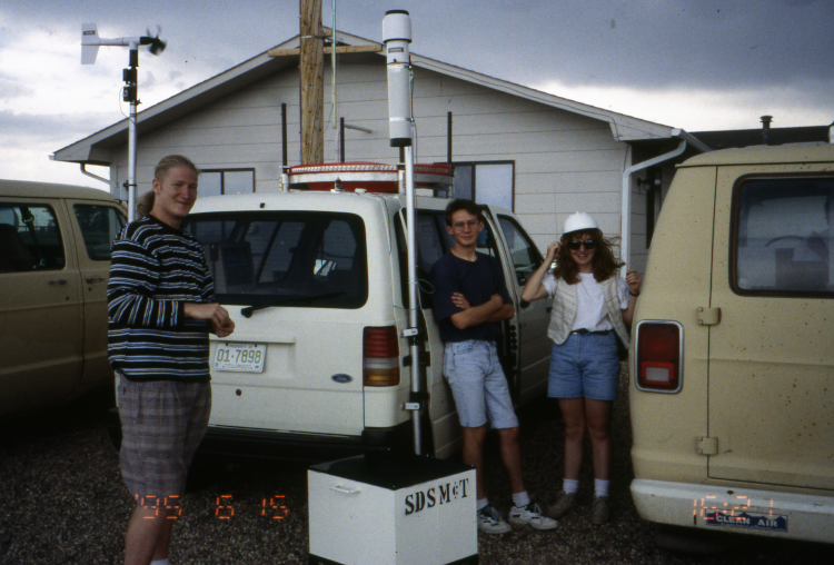
August 1988
21 May 1998
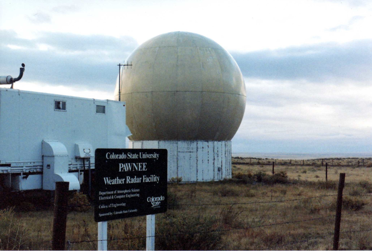
August 2006
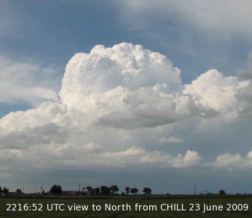
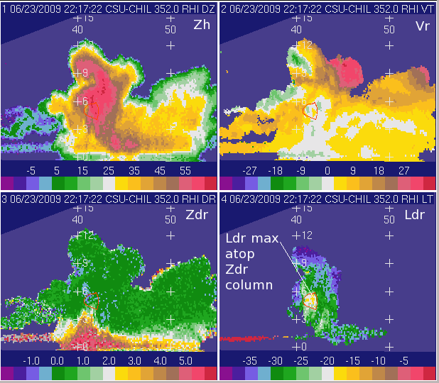
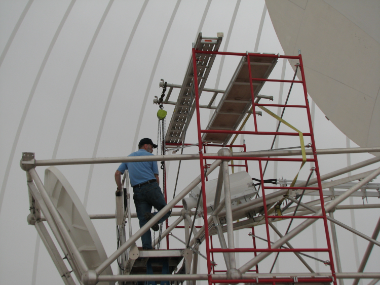
28 May 2013
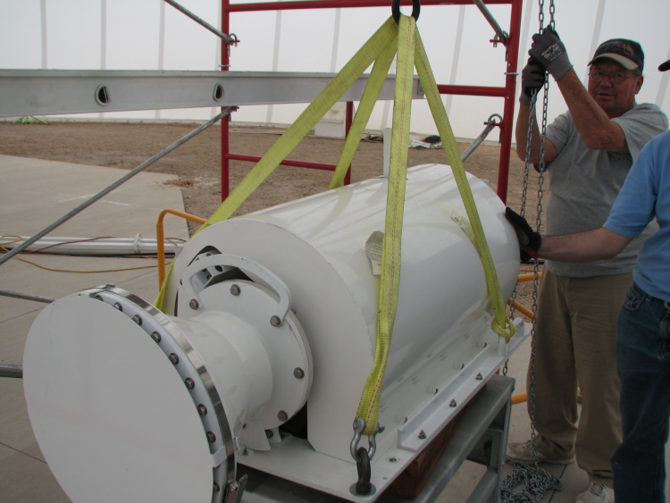
28 May 2013
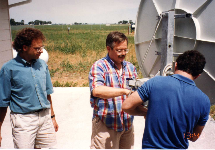
June 1993
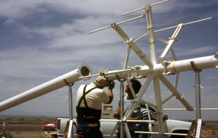
5 June 1996
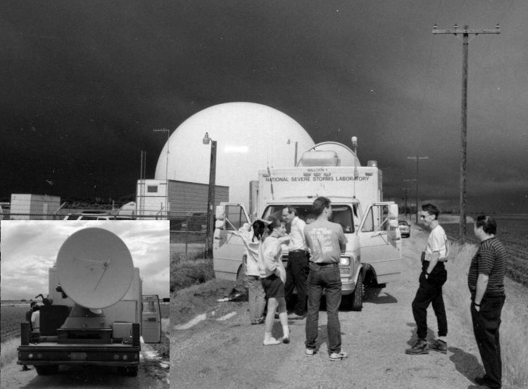
24 June 1995
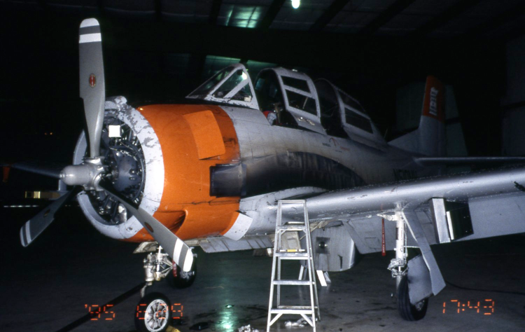
29 June 1995
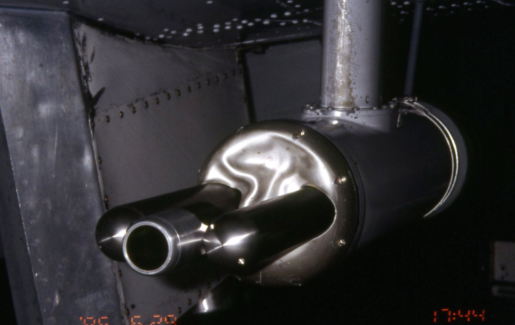
29 June 1995
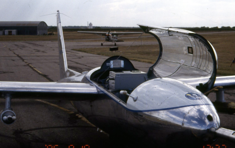
10 August 1995
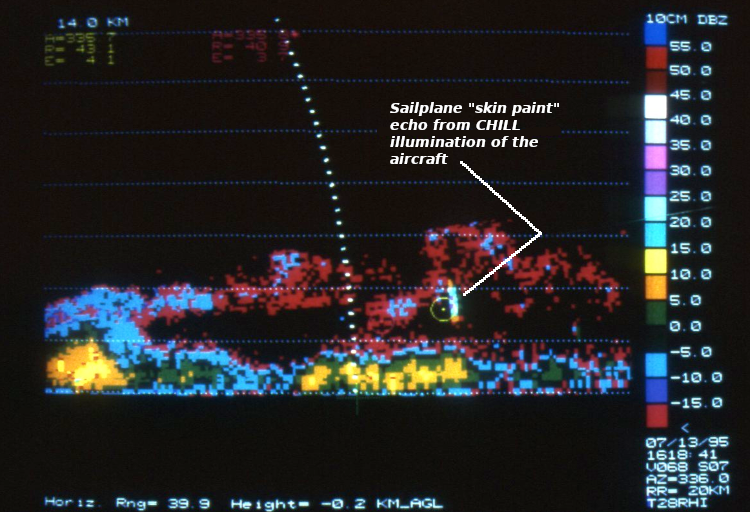
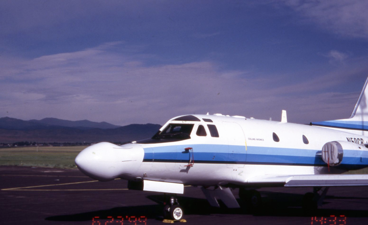
23 June 1999
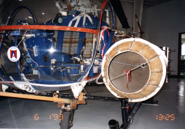
1 June 1993