A History of the CHILL Radar’s Technical Evolution
A History of the CHILL Radar’s Technical Evolution by Patrick C. Kennedy
Overview:
National Science Foundation (NSF) base funding for the CSU-CHILL radar ended in the early months of 2019. This marked the end of a 47-year period of research data collection that began in 1972 during the National Hail Research Experiment (NHRE). This historical summary is focused on the technical evolution of the CHILL radar that allowed it to remain active for such a long lifetime.
The radar’s lifetime has been broken into three phases: (1) The system’s original development and active deployment period (1972 – 1982). (2) The period of significant technical upgrades made possible by initiation of NSF base funding support while the radar continued to be hosted at Champaign, Illinois by the Illinois State Water Survey (ISWS), 1984 – 1990). (3) The transfer of the radar to Colorado State University (July 1990 – May 2019).
The series of NSF cooperative agreements that maintained base funding for the radar included a requirement for a facility manager position. In April 1988, the author assumed this position from John Vogel at the Illinois State Water Survey. Employment in this capacity continued through February 2019. This allowed direct involvement with much of time period 2 and essentially all of period 3. Most references for period 1 were obtained from boxes of archived files received from Gene Mueller, the Electrical Engineer primarily responsible for the radar’s original development. Historical material pertaining to the NHRE project was kindly supplied by Laura Hoff of the NCAR archives department. Nancy Wescott and Steve Hilberg took the time to extract a series of useful photographs from the ISWS archives. Dave Brunkow, who served as an electrical engineer with the CHILL radar during all three portions of the radar’s lifetime, also served as the primary reviewer of this document. The author is solely responsible for the selection of the elements included in this summary as well as any errors or omissions.
Phase 1: Initial Development and active deployment period:
The impetus for the original development of the CHILL radar came from a national interest in understanding hail-producing thunderstorms. It was hoped that this improved understanding could be applied to the development of weather modification techniques that could reduce hail damage to crops, structures, and vehicles. An overview of this national interest was provided at the First National Symposium on Hail Suppression jointly sponsored by NSF and NCAR and held in Dillon, Colorado in October 1965. A significant discussion topic at this meeting was the highly effective hail suppression results that had been reported by Soviet Union scientists in a high plains agricultural region of Russia (Battan 1969 provides an overview of weather modification activities in the late 1960’s).
Some of the Russian hail suppression methods were based on the coordinated collection of radar reflectivity data at both 10 and 3 cm wavelengths (S and X-band). In principle, areas where the X-band received signal level was reduced by Mie scattering while the S-band return was not were taken to give a clear identification of hailstones larger than ~1 cm in diameter. (It should be noted that the foundational concept of exploiting differences in the reflectivity of hailstones as a function of radar wavelength was first proposed by Atlas and Ludlam in 1961.) In the Russian operations, ground–based artillery shells carrying cloud seeding materials were fired into storm areas where the dual wavelength radar data indicated active hail growth was in progress. The introduction of the seeding agent was designed to deplete the supercooled liquid water concentration, thus reducing the hailstone growth rate.
The major outcome of the Dillon meeting was the recommendation to conduct a large scale, multi-year field project at a US location that would support a rigorous examination, and possible replication, of the Russian hail suppression efforts. During the latter half of the 1960’s, this recommendation was formalized into the planning of the National Hail Research Experiment (NHRE). NHRE data collection was centered in the northeast plains of Colorado where the climatological frequency of hail maximized. Figure 1 shows a sketch of the NHRE observing systems in the early months of 1969. The red annotations mark the two dual wavelength radar systems that were to be developed for NHRE.
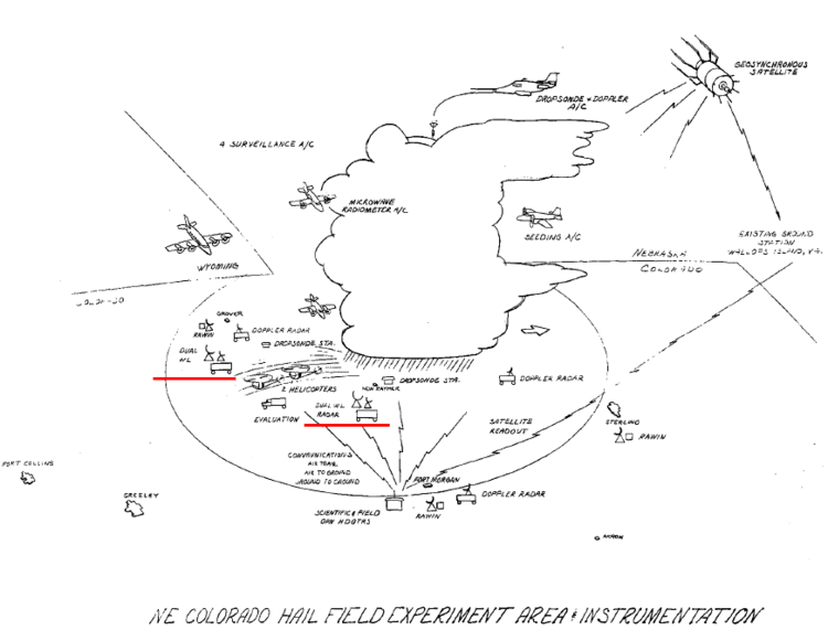
Figure 1: NHRE instrumentation sketch from the February 1969 preliminary planning document. The red underlines mark the locations of the two dual wavelength radars that were envisioned as being critical to the project. These radars were to be located near the towns of Grover and Ft. Morgan Colorado.
At this point in time, it was envisioned that the dual wavelength data would be collected by two separate radars with antenna control systems that would be slaved to maintain identical azimuth and elevation angles (Fig. 2).
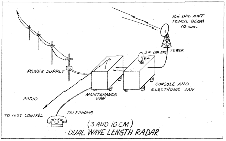
Figure 2: Schematic of the separate 10 and 3 cm slaved antenna systems to be developed for NHRE. (Figure from the NHRE preliminary planning document of January 1969).
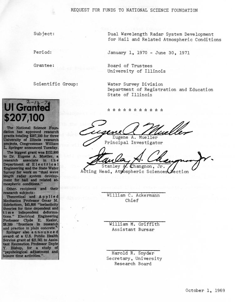
The responsibility for assembling one the two dual wavelength radars was assigned to NCAR. This radar eventually was named CP-2. The second radar was developed by a group composed of personnel from both the University of Chicago and the Illinois State Water Survey (ISWS). The combination of the names of these two institutions lead to the system’s becoming known as the CHILL radar. (The CHILL designation was not immediately applied at the start of the radar’s development: In a November 1970 memorandum of agreement between the University of Chicago and the ISWS regarding utilization of the radar outside of NHRE operations, the system was referred to as “the dual wavelength radar hail detector”.) The primary theoretical direction for the CHILL radar’s development came from Prof. Dave Atlas at the University of Chicago. Engineering and system integration activities were supervised by Dr. Gene Mueller at the ISWS in Champaign. (see Appendix A)
The 3 cm portion of both dual wavelength systems was based on WW2-era M33 tracking radar hardware. To match the radar sample volumes, the X and S-band antennas both had very similar main beam widths of ~1.0° and pulse lengths of 150 m. The CP-2 and CHILL S-band systems were both built around US Air Force surplus FPS-18 transmitters. The FPS-18 used a Klystron tube (VA-87) final power amplifier that output pulses with highly stable phase. This coherent pulse characteristic simplified the extraction of Doppler velocity information from the received signals. Two essentially identical ~9.5 m
diameter antennas, associated positioning systems, and air-supported radomes for CP-2 and CHILL S-and channels were ordered from Radio Systems Incorporated (RSI). This equipment was delivered behind schedule; the CHILL shipment left RSI on 10 September 1971 Fig. 3). The NCAR equipment arrived on a similar schedule; as a result, neither radar participated in the initial (1971) NHRE field season.
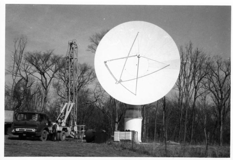
Figure 3: CHILL antenna and positioning system undergoing pre-delivery tests at manufacturer’s test facilities in approximately early 1971. Three equipment boxes near the base of the pedestal housed control equipment used with the motor-generator sets that drove the four 9 HP, low inertia motors in the antenna drive system (two motors on each motion axis). The feed horn could operate at either horizontal or vertical polarization. As built by RSI, the horn support struts lay in the H and V polarization planes. RSI built a second, identical antenna system that NCAR used for the Grover Radar (subsequently renamed CP2) used in NHRE. (Photograph from Gene Mueller’s files.)
As was mentioned in reference to the Russian hail suppression activities, the identification of hail through the recognition of Mie scattering effects at the 3 cm wavelength was one of the primary applications of dual wavelength technology in NHRE. A second dual wavelength quantity of interest was the mapping of high liquid water concentrations (LWC) based on the relative attenuation characteristics of the X-band returns. Conference presentations on both dual wavelength hail detection and LWC estimations were made at the 14th AMS Radar Meteorology Conference held in Tucson AZ on November 17 – 20 1970 (Eccles and Atlas p. 1 – 6, and Eccles and Mueller, p. 443-448. (Dr. Peter Eccles was an NHRE project scientist at NCAR). A major goal for the CHILL radar in NHRE operations, was to supply real time presentations of the dual wavelength hail signal. The Control Data Corporation (CDC) was contracted develop a custom-designed signal processor for the CHILL. In addition to performing the Eccles – Atlas hail signal calculation, the original version of the CDC processor was also capable of performing Discrete Fourier Transform (DFT) transforms in real time at up to 1024 range gates (when the transform length was limited to 32 points). The resulting power spectrum outputs supported analyses of mean Doppler (radial) velocity, radial velocity spectrum width, and noise power level. The real time calculation and recording of these data fields presented a major challenge to the computer technology around 1970. The initial assembly and testing of the CHILL radar were done at the ISWS field site located at the University of Illinois Willard Airport near Champaign, Illinois (Fig. 4).
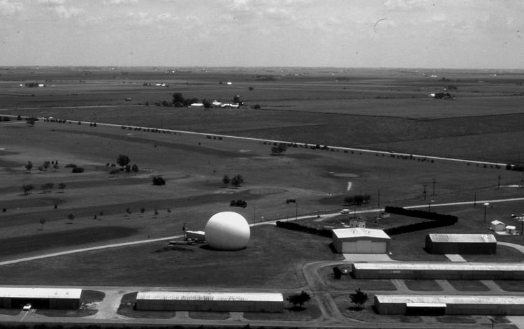
Figure 4: The CHILL’s original development and home base site near the general aviation hangar area in the northeast part of the University of Illinois Willard Airport (KCMI). The airport is located approximately 5 miles south of Champaign. The concrete foundation for the antenna and radome were broken up in 1993 after the radar had been transferred to Colorado State University.
Due to the antenna system delivery delays, both the CHILL and CP2 radars joined NHRE field activities during the second (1972) field season. CP-2 was installed at the project headquarters at Grover, Colorado; the CHILL was located ~65 km to the southeast of Grover near the Fort Morgan Airport (Fig. 5). These initial CHILL field operations proved to be a learning experience in terms of both transporting the radar equipment from Champaign to Fort Morgan (railroad shipment was used for the first and only time), as well as for establishing satisfactory radar operations at an isolated, remote site (Figs. 6 and 7). Data formatting errors written to magnetic tape by the CDC signal processor made reading several the 1972 CHILL tapes difficult. Despite the challenges encountered during this first field season, Carbone et. al. (1973) reported initial success with the Eccles-Atlas dual wavelength hail detection method based on the range derivative of the logarithm of the P10 / P3 received power ratio. This paper was based on the CHILL data collected on 25 July 1972.
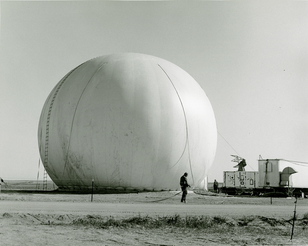
Figure 5. The CHILL radar’s first remote deployment to the NHRE project in May 1972. The radar site was on the east edge of the Fort Morgan, Colorado Airport. The radome was installed on 3 May 1972. (The presence of the rope ladder hanging on the left side of the dome suggests that this photograph may have been taken on the installation day.) The CHILL returned to this same site during the 1973 and 1974 NHRE field seasons. Photograph from the NCAR archives. This same picture was published in the 17 May 1972 edition of the Fort Morgan Times newspaper.
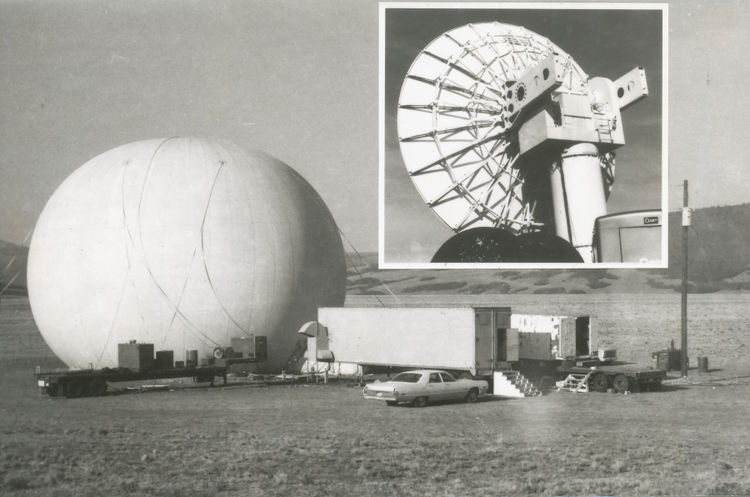
Figure 6: Typical CHILL installation during the radar’s intensive deployment period in the 1970’s. This radar site was located near Fairplay, Colorado. CHILL operations at Fairplay took place in 1974 and 1975. From left to right, the semi-trailers are: 1) Flatbed used to transport antenna components. The transverse-mounted generator on the front end of the flatbed provided backup power for the radome inflation blowers. 2) Enclosed trailer with heat exchanger hood extending from the left front wall housed the FPS-18 transmitter equipment. 3) M33 van mounted on a second flatbed trailer. This M33 van, referred to as the User van, provided an operator area for real time radar control, data display and recording, and radio communications. Inset above shows the S-band antenna backup structure. Picture from the ISWS archives.
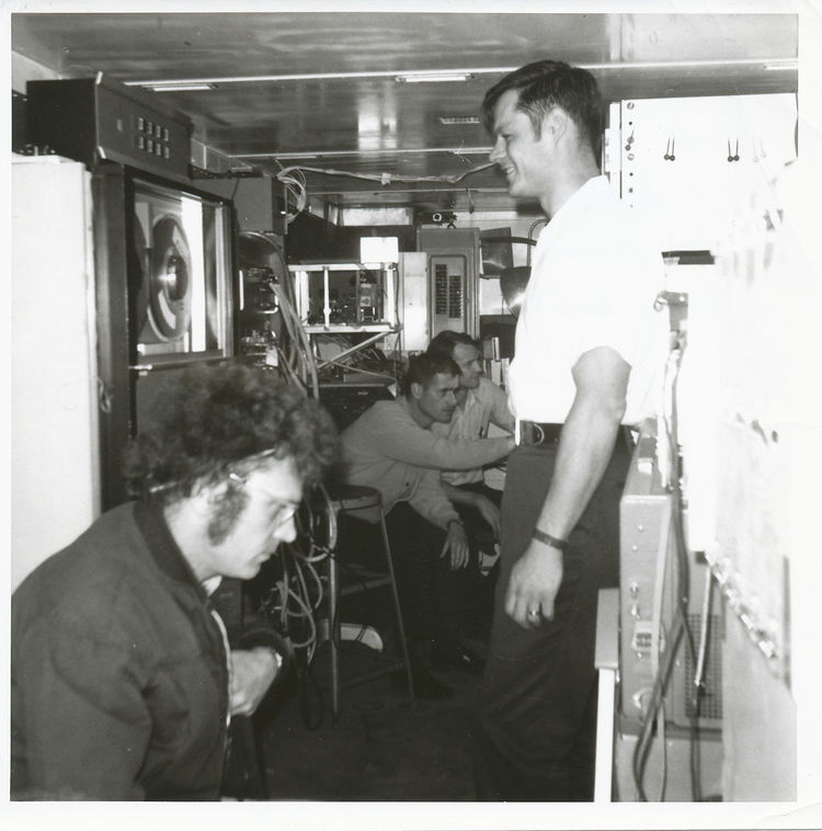
Figure 7: Interior of the User van in the 1970’s. Seen in the picture from left to right are: Griff Morgan (with pencil behind his ear). Gary Achtemeier (right arm extended). Ron Grosh (next to Gary). Ed Silha (standing and observing tape drive). Griff, Gary, and Ron were all ISWS meteorologists involved with various aspects of thunderstorm and hail research. Ed Silha was an electrical engineer who worked on the development and early deployments of the CHILL radar.
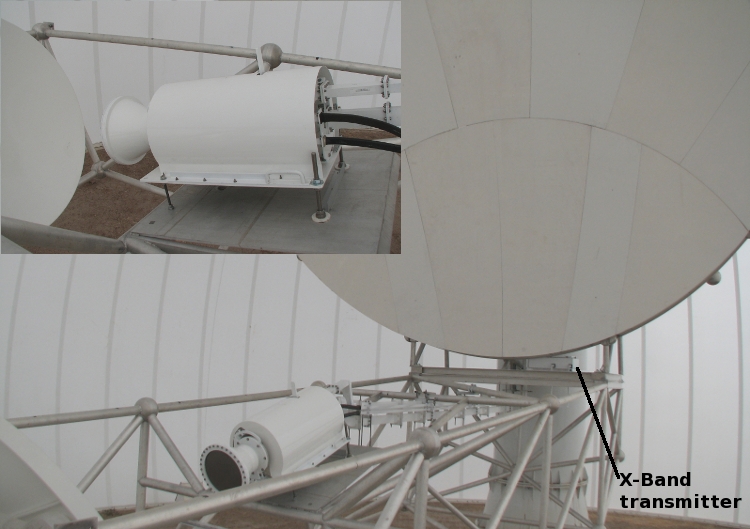
The CHILL radar returned to the Fort Morgan site for the 1973 and 1974 NHRE field seasons. Based on the accumulating operational experience, several CHILL system improvements were made during this time period. Among the more significant upgrades were the relocation of the 3 cm wavelength M33 transmitter and antenna to the main S-band pedestal for the start of the 1973 season (Fig. 8). This shared pedestal arrangement kept the two antennas pointing in the same direction all the time, thus eliminating the relative pointing angle errors associated with attempting to slave two independent pedestals together. The implementation of a more flexible antenna motion control system also greatly improved the ability to collect complete volume scan data from the thunderstorms that were targeted during NHRE.
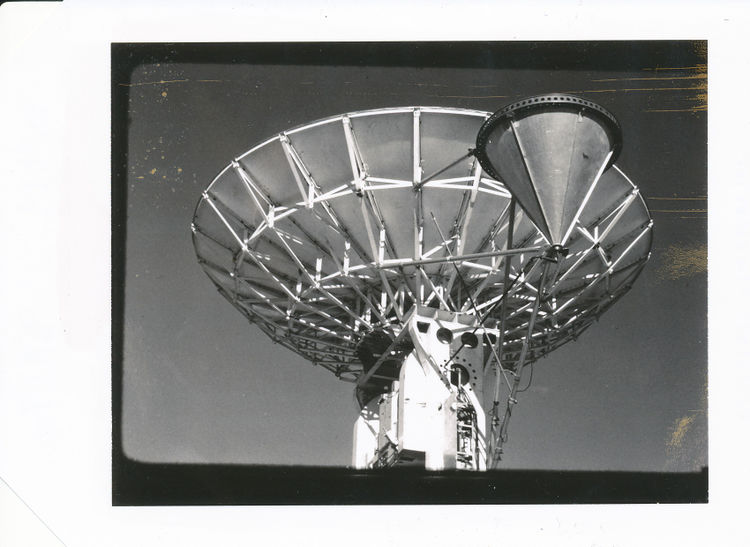
Figure 8: Installation of the rear-fed, X-band antenna onto the CHILL S-band antenna. This modification was done prior to the second (1973) NHRE operating season. The narrow equipment mounting assembly seen on the main antenna counterweight contained the X-band transmitter. NCAR’s CP2 radar adopted this shared pedestal arrangement approximately 7 years later in preparation for the CCOPE project in 1981.
Preliminary analyses of the random seeding results obtained through the 1974 season lead to a high-level reconsideration of the overall NHRE project experimental design. Hail mitigation efforts were curtailed in favor of the collection of basic thunderstorm environment and structural data (i.e., observations from radiosondes, instrumented aircraft, and selected research radars.) This project reorganization lead to 1974 being the final NHRE field season for the CHILL radar. Following the NHRE participation, the radar continued an active deployment schedule to support a number of field projects.
The data in the following table of major project support from NHRE through the Cooperative Convective Precipitation Experiment (CCOPE) in 1981 was selected from a summary assembled by Gene Mueller:
>>>> construct table 1 here
Table 1 footnotes:
CMI is the University of Illinois Willard Airport just south of Champaign, Illinois. CSU is Colorado State University. LAP is Laboratory for Atmospheric Probing at the University of Chicago. OSU is Ohio State University. NIMROD is Northern Illinois Meteorological Research on Downbursts. SESAME is Severe Environmental Storms and Mesoscale Experiment. UVA is University of Virginia. VIN is Virginia-Illinois Network. ISWS is Illinois State Water Survey. PACE is Precipitation Augmentation for Crops Experiment. CCOPE is Cooperative Convective Precipitation Experiment
During this period of CHILL radar high utilization, the nature of the user-requested measurements evolved. While the original RSI-built S-band antennas for CHILL and CP-2 were delivered with dual linear polarization feed horns, the NHRE era operations were centered on dual wavelength vs. dual polarization measurements. This emphasis changed with the publication of a seminal paper by Tom Seliga and V.N. Bringi in the January 1976 issue of JAM: “Potential use of radar differential reflectivity measurements at orthogonal polarizations for measuring precipitation.” The paper presented electromagnetic scattering calculations that indicated that the typically expected distributions of raindrop equilibrium shapes and sizes should generate a statistically measurable difference in the radar signal levels received at horizontal vs. vertical transmit polarization states. This proposed measurement of “differential reflectivity” (Zdr) would provide a representation of the median drop diameter (Do) in the population of drops within the radar pulse volume.
The first domestic US efforts to collect Zdr data to test these theoretical expectations were done with the CHILL radar during the deployment to Anadarko, Oklahoma in 1977 (Seliga et al., 1979). (Other investigations into dual polarization radar technology were being made in Canada at the Alberta Research Council and in the UK by the Chilbolton radar group.) It seems likely that Gene Mueller’s support of these exploratory Zdr measurements may have grown from his own Ph. D dissertation work (completed in 1966). Gene’s graduate research was centered on data collected by an automated camera system that he designed to captured one-minute samples of freely falling raindrops. The analysis procedures for the resultant photographs required the use of calipers to measure the horizontal and vertical dimensions of the magnified drop images. Thus, Gene was well aware of the oblate shapes that raindrops larger than ~1-2 mm in diameter assumed. (It should be noted that an earlier version of the ISWS drop camera also resolved oblate raindrop shapes Jones, 1959). The tendencies for falling raindrops to develop oblate shapes and maintain preferred orientation angles were essential to the generation of the Zdr signal in rain.
For the initial 1977 Zdr measurement experiment with the CHILL radar, switching between the horizontal and vertical transmit polarization states was done using a motor-driven waveguide switch. Inside the switch, the physical rotation of a waveguide piece with a 90° H plane bend was used to selectively route the transmit / receive signal path to the horizontal or vertical ports of the antenna feed horn. While the switch was in transit between its H and V positions, transmitter triggering had to be inhibited to avoid destructive high power reflections from the moving waveguide section. The net result was that separate blocks of H and V polarization returns were obtained at ~2 second time intervals. This mechanical switching scheme necessitated very slow antenna scan rates (stationary to ~1° s-1), but the resulting dual polarization data was adequate to prove the feasibility of making meaningful Zdr measurements. Additional Zdr data collected by the CHILL radar while operating at the Governor’s State University site in the southern fringes of the Chicago area in August, 1978 demonstrated an improvement in radar-estimated rainfall amounts when both conventional reflectivity and Zdr data were used (Seliga et. al, 1981).
The CHILL’s Zdr measurement capabilities were substantially improved in July 1981 during the CCOPE project (final remote deployment in Table 1). The slow speed, motor-drive waveguide switch that had been used to change the transmit / receive polarization state between horizontal and vertical was replaced with an electrically switchable circulator that was custom built by Raytheon. This “fast switch” had no moving parts, giving it the operational speed necessary to change the polarization state on a transmitter pulse to pulse basis. One can think of the switch as a circular waveguide path (Fig. 9). Acquiring the H and V signal returns at the typical pulse repetition interval of ~.001 s vs. the ~2 seconds with the slow, motor-driven switch reduced the statistical uncertainty of the Zdr measurement
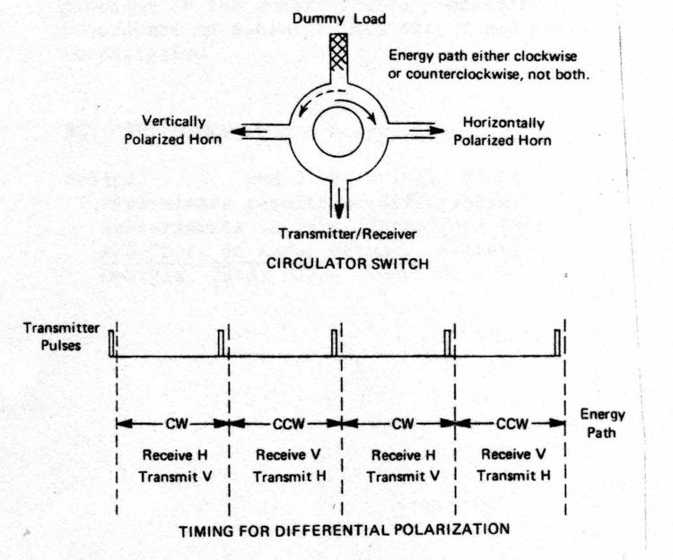
Figure 9: Operating schematic for the Raytheon polarization switch. This switch used the magnetization state of ferrite material to control the direction in which microwaves propagated around a circulator. The dashed vertical lines in the lower portion of the figure show the application of DC current pulses sent through coils surrounding the circulator’s ferrite material. Alternating the polarity of these current pulses reversed the direction of the ferrite’s magnetic fields, varying the microwave propagation direction through the circulator between the CW and CCW directions shown in the upper portion of the figure. The speed with which these magnetic field reversals could be done allowed transmit polarization to be changed on a pulse to pulse basis, improving the Zdr measurement speed. The CHILL radar collected the first Zdr data using the Raytheon switch in late July 1981 during the CCOPE project. Raytheon switches were fitted to the NCAR CP2 and the NSSL Cimarron radars in 1983 and 1986 respectively. The drawing in this figure was scanned from a radar conference preprint written by Gene Mueller in the early 1980’s.
Research weather radar technology advanced considerably during the first decade of CHILL operations (1972 – 1982, see Table 1) The NSSL Norman Doppler radar became operational in 1971. It was joined by the NSSL Cimarron Doppler radar in 1973. This pair of S-band Doppler radars collected coordinated volume scan data sets supporting the synthesis of three-dimensional air motions within severe thunderstorms. Similar dual-Doppler analyses were first generated in NHRE during the 1973 season using data collected by two transportable X-band radars developed by the Boulder, CO NOAA laboratory. NCAR’s pair of transportable C-band (5 cm wavelength) Doppler radars, CP3 and CP4, became operational in 1974 - 1975. This expansion in the utilization of Doppler measurements was facilitated by the implementation of the autocorrelation / pulse pair calculation method for the estimation of mean radial velocity. The pulse pair technique was computationally much more efficient than the earlier DFT-based spectral velocity estimation techniques (Sirmans and Doviak, 1973). The routine availability of radial velocity values at all range gates promoted the development of color displays for the presentation of both real time and played-back radar data (Gray et al., 1975). Finally, during the latter half of the 1970’s, the control of radar system operating parameters (PRF, etc.) and antenna scan control (rotation rate, PPI vs. RHI scan mode, etc.) was increasingly done via interactive computer interfaces. This improved data collection reliability and flexibility in comparison to the physical setting of control panel switches and thumb wheels that had originally been used to define the radar operating parameters.
The CHILL radar’s adoption of technical upgrades during the 1970’s was impacted by the frequent deployment activities summarized in Table 1. (Nevertheless, the pulse pair velocity calculation was implemented by Ed Silha in the winter of 1975 – 1976, and a color display was instituted in 1979.) A major factor in the deployment frequency was the lack of base funding for the radar. Except for a small amount of State of Illinois salary support (typically ~1 FTE technician), funding for the radar and its staff came only from individual field project budgets. These episodic funding limitations and uncertainties left little money and staff time available for radar system maintenance and upgrade efforts. In the post-CCOPE period (late 1981 – early 1982), the CHILL radar’s reliability had deteriorated to an unsatisfactory level, with one of the primary problems being intermittent, frequent failures in the CDC signal processor. Presumably, the vibrations that the signal processor had been subject to during the repeated deployments had caused intermittent connection failures to develop in many of the processor’s circuit card edge connections.
Phase 2) Start of NSF base funding support at ISWS
In view of the radar’s degraded ability to collect research-quality data and limited funding for hardware improvements in late1982, the ISWS Atmospheric Science Section management group explored various future pathways for the CHILL radar. Internal discussions lead by Stan Changnon, Bernice Ackerman and Richard Semonin considered several possibilities including mothballing of the equipment or transferring the radar to NCAR or NSSL. During a trip to NSF headquarters in late January 1983, Changnon presented the idea of convening a workshop to gauge the level of community support for upgrading the CHILL system to provide continued research operations with NSF base funding. Dick Dirks and Ron Taylor at NSF reacted favorably to this idea and agreed to fund a workshop to review the CHILL’s status and future. This workshop was held at Champaign Illinois on June 14 – 16 1983. The workshop panel was composed of 17 representatives primarily from NCAR, NOAA and past CHILL users. The consensus of this group was that the atmospheric science research and education communities would benefit from the continued availability a technically upgraded CHILL radar. To this end, a proposal was submitted to NSF specifying the workshop-recommended upgrades to the radar and stating the desired level of multiyear base funding support. The proposal resulted in a 5-year NSF grant (NSF ATM-8320095) that started on 1 May 1984.
The general plan of this initial cooperative agreement with the NSF called for the first two years to be devoted to technical upgrades to the CHILL followed by a transition to data collection activities during the final three years of the agreement. (The primary technical upgrade was the replacement of the CDC signal processor. It was decided that no immediate refurbishment efforts would be put into the CHILL X-band channel.) Ultimately, the SP20 signal processor designed and built by Lassen Research was selected. As proposed by Lassen, the SP20 was an innovative design using digital signal processing chips that had not yet reached production status. A major advantage of the SP20 was its programming flexibility. Signal processing calculations and I/O procedures could be changed via microcode software vs. the physical wiring changes that had been necessary with the CDC processor. In addition to the signal processor replacement, other CHILL system upgrades made under the initial cooperative agreement included:
· An Adage real time color display processor allowing the interactive selection of 4 data fields with user adjustable image centering, magnification, and time lapse looping capabilities. These were useful improvements upon the performance available from the original TI-990 based color display hardware.
· A MicroVAX computer-based system for user control of radar system operation. The associated interactive antenna scan control software simplified making real time data collection adjustments to compensate for echo evolution and movement.
· Improvements to the radar’s RF chain and receiver hardware for increased sensitivity, stability, and dynamic range.
· Dual 9 track tape drives working in “ping pong” mode to prevent data recording interruptions during tape changes. The tape could also be replayed from these drives through the Adage color display system. This allowed immediate perusal of the data to examine both data quality and to allow users to make initial appraisals of the data’s meteorological content.
· Interior improvements to the user van to provide a quieter, better temperature-controlled environment in which both real time data collection and initial data review activities could take place.
Delays in the delivery of some of the newly designed chips prevented the SP20 from entering service as planned during the summer of 1986. (CHILL data was collected that summer for the Precipitation Augmentation for Crops Experiment (PACE) project using basic signal processing calculations that were temporarily programmed in the SKY320 data buffering hardware.) The SP20 was delivered on 17 March 1987. Initial data collection using the SP20 and most of the other upgraded CHILL hardware took place when the radar was deployed to Dickinson, North Dakota during portions of the June – July 1987 period (Fig. 10). Three research aircraft also participated in the North Dakota project. The real time locations of the aircraft were included in the Adage color display based on a stream of transponder report data relayed via phone line from Research Aircraft Tracking System (RATS) equipment that was temporarily installed at the Watford City ND FAA radar site. (The RATS equipment was designed at NCAR. The assembly and checkout of the CHILL version of the RATS hardware was a cooperative effort between NCAR and ISWS.) Following the North Dakota deployment, the upgraded CHILL system was successfully used in several research projects done at the radar’s home base radar site at the Champaign / CMI airport (Ramamurthy et al. 1991) during the 1988 – 1989 period (i.e., the final years of the original NSF cooperative agreement).
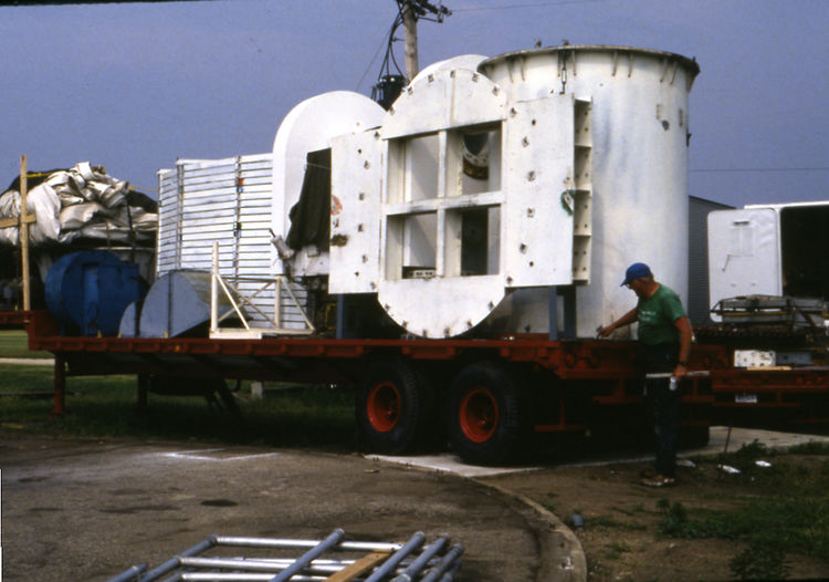
Figure 10: CHILL antenna trailer as loaded in May 1987 for remote deployment to Dickinson, North Dakota. The circular section with four square openings is the adaptor plate that connected the antenna’s central hub to the two counterweight assemblies. The pedestal extension tubes are concentrically loaded at the rear of the trailer. Going forward along the trailer, the motorized upper portion of the pedestal, stacked antenna backup structure trusses and radome inflation blowers (painted blue) are visible. The collapsed radome is strapped down on the front end of the trailer. This antenna packing procedure allowed the CHILL radar to be deployed using only three semi-trailers: The antenna trailer seen here, the FPS-18 transmitter van, and the M33 user van. In the photograph above, the trailer’s tires are resting on the concrete pad extension used for the radome airlock entryway. Gene Mueller is seen checking the load security.
Phase 3) Transfer from ISWS to Colorado State University
By 1989, the CHILL radar technical upgrades identified in the 1983 workshop and implemented during the initial cooperative agreement with the NSF had been demonstrated. Review and allocation of the radar’s usage had been added to the deliberations of the Observing Facilities Allocation Panel (OFAP) meetings conducted twice a year at NCAR. NSF decided that hosting of the CHILL radar during the second cooperative agreement base funding period should be opened for competition among interested universities. In January 1990, Colorado State University (CSU) was selected as the next host institution for the CHILL radar Facility. A major element in this selection was the complementary expertise of two of the PI’s in the CSU proposal: Atmospheric Science Prof. Steve Rutledge had considerable experience in the use of research radar data for investigations of both cold and warm season mesoscale precipitation systems. Electrical and Computer Engineering (ECE) Prof. V. N. Bringi had done seminal work in the development and application of dual polarization weather radar technology. Furthermore, at CSU, these two academic departments were both components of the College of Engineering, streamlining the administrative operation of the radar as an NSF Facility.
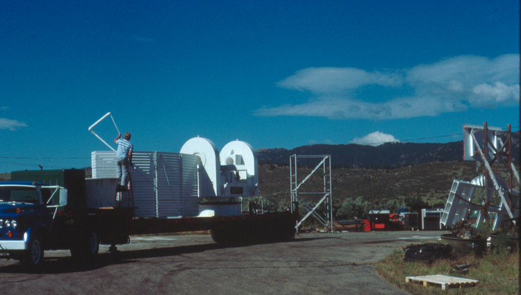
Figure 11: CHILL antenna trailer shortly after its arrival at the CSU Foothills Campus in late June 1990. Atmospheric Science Department student employee Dave Wood is handling an antenna truss. The antenna equipment was pressure washed following the trip from Champaign.
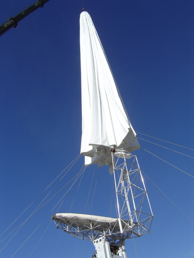
The CHILL radar equipment arrived at the CSU Fort Collins Colorado Foothills Campus in late June 1990 (Fig. 11). Due to the proximity of the main campus to the front range foothills of the Rocky Mountains, beam blockage made radar operations in the immediate campus area unfeasible. The strong, mountain wave-related winds that often affect the Ft. Collins area during the winter season were also a significant consideration in the reliable operation of the CHILL’s air-supported radome. As a result, a CHILL radar operating site was established on a portion of the research farm property owned by CSU near Greeley, Colorado (~45 km east of the foothills).
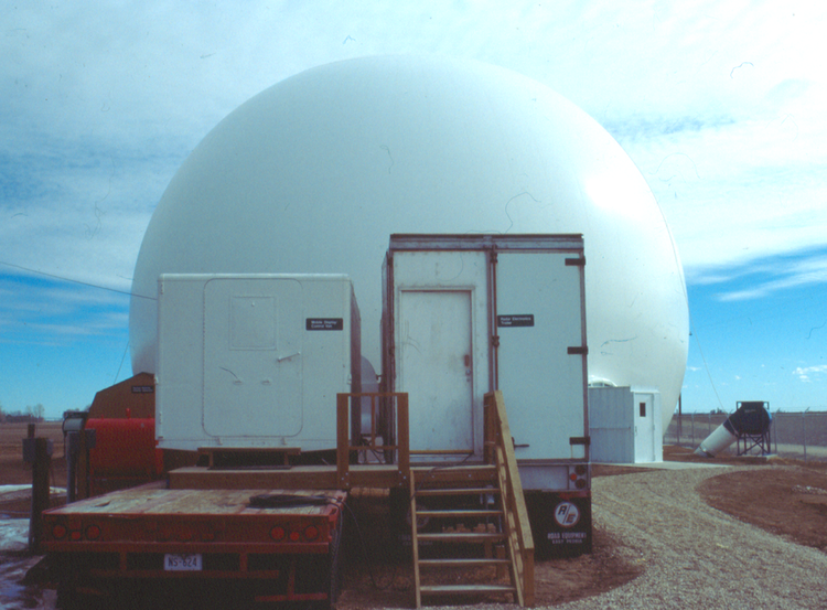
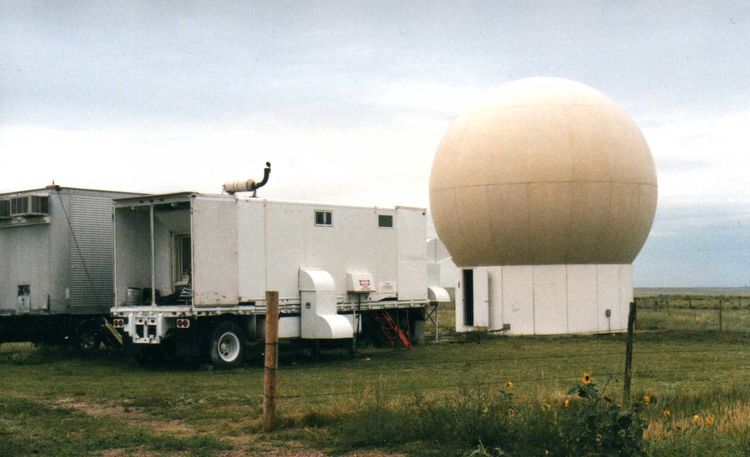
Figure 12: CHILL radar equipment as originally installed in August 1990 at CSU’s site located next to the Greeley, Weld County Airport. For easier access, the M33 user van (left) and FPS-18 transmitter van (right) were parked next to each other and joined by a shared wooden deck. A new, larger radome identical to the one used by the CP2 radar was installed as a part of the move from ISWS to CSU. The new dome used an airlock designed around an aluminum box passageway. Dome inflation air was delivered through ducts buried under the basic radome foundation. These two design features are seen near the right edge of the picture.
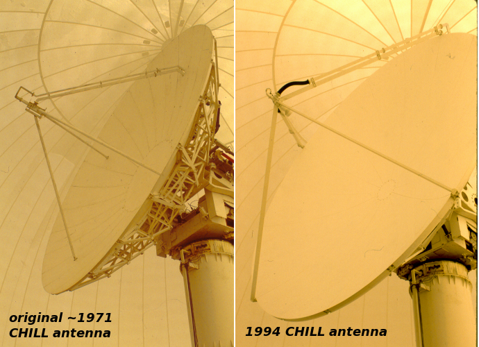
The radar, now known as CSU-CHILL, was initially assembled at the Greeley site in late August 1990 (Fig. 12). To remove the feed horn support struts from the horizontal (H) and vertical (V) polarization principle planes, the antenna reflector was rotated 45o around the boresight axis during the assembly process. This rotation reduced the disturbances that the feed support struts caused in the H and V polarization main beam and sidelobe radiation patterns. The improved H – V antenna pattern matching reduced artifacts in the dual polarization data. This antenna modification was the start of general efforts made by the CSU ECE group to improve both the quality and quantity of the radar’s dual polarization data. These endeavors were aided by the addition of Prof. V. Chandrasekar to the CSU ECE faculty during the fall of 1990. CSU-CHILL technical improvements lead by Bringi and Chandra in the early 1990’s included: (a) Increased collection of time series data to examine base-level data quality. (b) Implementation of differential propagation phase, HV correlation coefficient, and Linear Depolarization Ratio (LDR) calculations in the SP20. (c) Measurement of the radiation patterns of the rotated antenna using a remotely located S-band signal source; an antenna system gain measurement was also made using a metal sphere suspended from a tethered balloon.
These antenna performance measurements indicated that the original late 1960’s era CHILL antenna design was limited in its ability to collect comprehensive, research quality dual polarization data. (It should be noted that the original antenna design specifications only called for the basic capability to transmit and receive linear H and V polarizations). These antenna performance findings led to the development of a tightened set of antenna specifications. In particular, the matching of the H and V radiation patterns in both the main beam and sidelobe regions needed to be improved. Also, the integrated cross polar ratio (ICPR) was to be held to a low level (under – 30 dB) to permit LDR measurements from a wide variety of meteorological conditions (i.e., vs. more than just high depolarization conditions such as melting layers, etc.) In 1993, RSI proposed meeting the CSU antenna performance requirements based on a prototype S-band antenna that they had built to compete for the contract to supply the production antennas for the NEXRAD network.
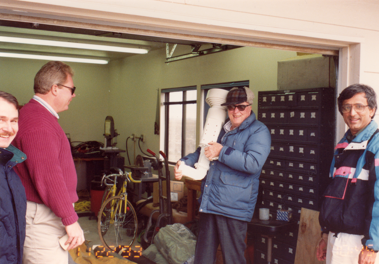
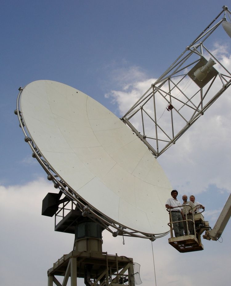
Figure 13: Unpacking of the feed assembly for the new CSU-CHILL antenna on 22 November 1993. Seen in the picture from left to right are: Prof. Kultegin Aydin (visiting from Penn State EE Department), Prof. Steve Rutledge, Gene Mueller, and Prof. V. N. Bringi. Gene’s hands are grasping the H and V polarization waveguide connections on the new OMT / feed horn assembly.
RSI’s proposal was accepted, and the new antenna was delivered to the CSU-CHILL site in November 1993 (Fig. 13 and 14). Data collection with the new antenna was initially done during the early months of 1994 during NCAR’s Winter Icing and Storms Project (WISP 94). These operations confirmed that the new antenna’s ability to collect cross polarization (LDR) data was being limited by the isolation levels achieved by the Raytheon switchable circulator. Even when optimally tuned, the Raytheon switch could only reduce the transmit power level going to the “off” antenna port to a level ~24 to 26 dB below the level in the “on” polarization port. This isolation level was satisfactory for the switch’s original Zdr measurement design objective. The leaked power in the off / cross channel polarization sense channel prevented measuring LDR values down to the ~ -30 dB level that the new antenna was capable of.
People
