Radar: Tomorrow's Raingauge
A look at the research weather radar technology of the early to mid 1950s, provided by excerpts from the film "Radar: Tomorrow's Raingauge".
Introduction
In May of 1954 the Illinois State Water Survey (ISWS) produced a 16mm film that summarized some of the results of the organization's weather radar research activities. Portions of this film have been converted to a digital format suitable for internet dissemination. The primary intent is to provide a look at the weather radar technology that was used in the early efforts to remotely estimate rainfall. Since the original film was silent, Dr. E. A. Mueller, who was a central figure in the ISWS radar meteorology group, provided much of the following explanatory material.
Video
Early installation of the APS-15
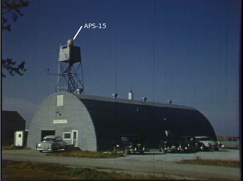
The opening images of the film show the small APS-15 radome mounted on the top of an ex-US forest service fire observation tower that had been installed next to a Quonset hut building at Willard Airport. In a subsequently enlarged form, this Quonset hut continued to house the ISWS radar engineering group through 1990. The APS-15 was an X-band airborne surveillance radar that was originally developed for use on navy patrol aircraft in World War II.
The APS-15 operated in continuous 360° PPI scan mode at a fixed elevation angle. It collected much of the data that was used for early rainfall estimation and severe weather identification studies at ISWS.
Later installation of the CPS-9
The next view of the radar tower was taken at a later time and contains an expanded array of radar equipment. The names of the various radars are shown in the following annotated image:
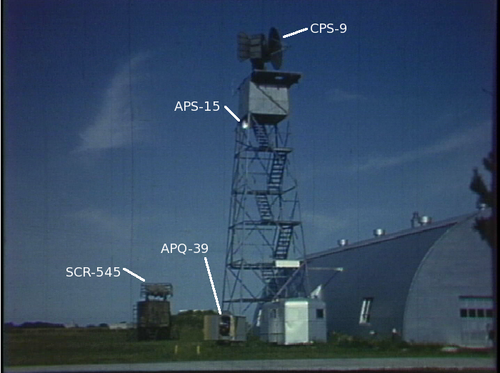
Selected remarks on these radars:
- SCR-545: This was a military surplus aircraft detection radar that included a 10 cm wavelength target search capability. ISWS sought to investigate the use of this longer wavelength for meteorological purposes. Ultimately, this radar saw very little ISWS use.
- APQ-39: In contrast to the SCR-545, this radar operated at a wavelength of 0.866 cm. This short wavelength made it primarily useful for studies of non-precipitating clouds. It was also surplus WWII military equipment. ISWS constructed a modified mounting scheme that allowed the radar to make 180 degree “over the top” RHI scans while slowly rotating in azimuth.
- APS-15: This is the same radar that had been installed on the top of the tower in the opening scene. At this later time, the newer CPS-9 had taken over the top of the tower position.
- CPS-9: This was the first post-war era radar that was specifically designed to make weather observations. It operated at X-band, had a peak transmit power of 250 KW, and used a 7.75 foot diameter antenna that generated an ~1 degree beamwidth. The antenna was controllable about both the azimuth and elevation axes (i.e., PPI and RHI scans could be done at selectable fixed angles.) This particular CPS-9 was a pre-production prototype that Raytheon had originally shipped to MIT for basic electronic performance testing. Once this initial testing was completed, the radar was transferred to ISWS. One of the initial CPS-9 experiments involved comparing the X-band observations made by the narrow beam CPS-9 against the wider (3.5 degree) beam APS-15.
TPS-10
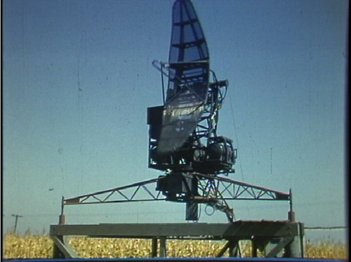
The TPS-10 was a war surplus height finding radar. The antenna pattern was ~0.7 degree wide in the vertical direction and ~2 degrees wide in the horizontal plane; the radar operated at X-band. At ISWS, the TPS-10 data was used primarily for studies of convective echo life cycles.
CPS-9 control console
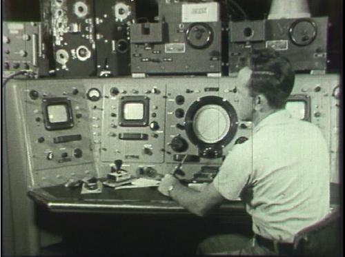
The various sloped-front consoles housed the operating controls and multiple CRT displays for the CPS-9. The additional equipment boxes located on top of the CPS-9 control assembly were associated with the other ISWS radars. The operator seated at the control panel is ISWS Electrical Engineer Jack Miller (deceased). Raytheon would retain this basic radar control panel design when they started commercial production of the 10 cm wavelength WSR-57 radar later in the decade.
Drop Camera
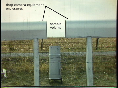
The drop camera was conceived and built at ISWS, with Douglas M. A. Jones being primarily responsible for the basic optical concepts and Gene Mueller designing the overall instrument including the stroboscopic flash electronics and automated camera systems. The camera was designed to automatically collect a sequence of back-lit images of freely-falling raindrops. The primary goal was to improve the understanding of radar backscatter intensity through detailed observations of raindrop size distributions. The realization of this goal required the tedious manual measurement and counting of the individual drop images in the photographic records. Ultimately, drop camera observations were made in 10 different geographic locations distributed through various climatic regimes (Alaska, SE Asia, etc.) Evidence that larger diameter raindrops assumed flattened shapes was also apparent in the drop camera images. (The exploitation of this in terms of the measurement of differential reflectivity, etc. began some 20 years later.)
APS-15 data animations
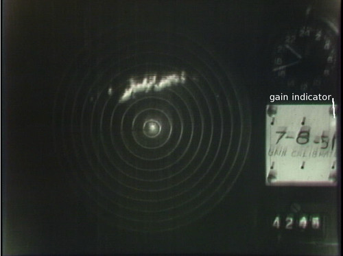
In the 1950's, radar data was recorded by making a photograph of each sweep on the PPI display. The data animation sequence shown in the film presents the time lapse sequences from two convective precipitation events as viewed by the APS-15. This radar also captured a similar image sequence during a tornado on 9 April 1953.
The brightness dynamic range of both the CRT phosphor coating and the camera film were limited. To increase the echo intensity measurement range, ISWS modified the radar receiver so that the gain could be reduced in several fixed steps. Thus, the shrunken echo area that remained at a reduced gain setting could be associated with a returned power level greater than a known value. Illumination of the various lamps around the date annotation in the image indicated the gain setting that was in use. The assembly of echo intensity contour plots involved manual tracing of the of the echo edges seen at the sequence of gain steps onto a common sheet of translucent paper.
Example rainfall analyses
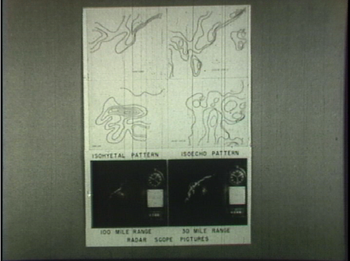
Based on the manually prepared echo intensity contour plots, a time history of the received power was developed over a network of rain gauges operated by ISWS; this network was centered approximately 20 statute miles west-northwest of Willard Airport. The images shown in the film depict an example comparison of the radar-based rainfall amounts against the gauge accumulations. In the early 1950's, the methods of relating radar signal strength to rain rate were still evolving. For example, the radar equation correction factor for the non-uniform power density across the pulse volume was not published by Probert-Jones until 1962. Attenuation of the 3 cm wavelength signals was an additional complication.
Summary
The pioneering efforts contained in this 1954-era film document the technical challenges that existed in the early days of radar meteorology. The collection of analogue data using WWII-surplus radar equipment and the time-consuming manual analysis of the resultant photographic images are primitive methodologies in comparison to current practices. Never the less, the advances and failures of these early efforts guided the subsequent evolution of weather radar technology. Much of the foundation of modern day methods for estimating rainfall using digital signal processing techniques applied to dual-polarization radar data was laid in the 1950's.