Installation of the Dual Offset Feed Antenna
Photographic Summary of the Antenna Installation
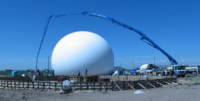
The installation of the CSU-CHILL’s new dual-offset feed antenna began in December, 2007. This marked the final stage of a long preparation process: The dimensions of the new antenna required the use of a larger diameter radome. (The existing dome was beyond its designed service life and was due for replacement.) Also, the concrete foundation for the existing radome was located near the southern boundary of the Greeley radar site property. This limited clearance made it impossible to simply enlarge the existing concrete foundation to provide an anchorage for the larger new radome. Instead, an entirely new radome foundation was designed and built at a more centralized location within the site boundaries. Figure 1 shows the pumping of concrete into the new antenna foundation in early July, 2007.
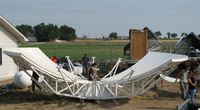
The existing radome and antenna were disassembled on 11 July, 2007. Prof. Chandra’s REU students provided valuable assistance in these efforts, particularly in the disassembly of the of the center-fed antenna’s reflector (Fig. 2). Once the antenna pedestal was accessible for detailed inspections, it became apparent that main azimuth bearings were severely worn and that portions of the slip ring assembly had already suffered a partial mechanical failure. The conduct of the required pedestal overhaul efforts was greatly facilitated by Jack Fox of NCAR’s Design and Fabrication Services section. To reduce the overall down time, Jack designed a system of spacers that allowed an “off the shelf”, commercially-available ball bearing to be installed in the lower bearing position. (A replacement for the main, weight-carrying upper bearing was available in the CHILL spare parts inventory.) To provide an indoor work space for the repairs, NCAR made room for the CHILL pedestal in their Marshall Colorado shop building. During the August – December 2007 period, CSU-CHILL master radar technician Bob Bowie spent the majority of his time at the NCAR Marshall shop replacing the worn azimuth rotation components in the CHILL antenna pedestal.
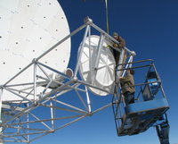
The repaired pedestal was returned to the CHILL site in mid-December 2007 and, under the direction of a field technical group from the manufacturer (Vertex-RSI), installation of the dual offset feed antenna was immediately started. The final stage of this assembly process involved the installation of the sub-reflector at the end of the feed boom (Fig 3). Vertex-RSI then conducted photogrammetric analyses of the fully assembled antenna to ensure correct spatial positioning of the critical antenna components (i.e., the feed horn, main and sub-reflector surfaces).
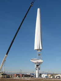
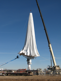
Once the photogrammetric measurements of the antenna were completed during January, 2008, attention turned to the installation of its new protective radome. The radome is an air-supported structure made of nylon fiber-reinforced vinyl material. While deflated, the radome envelope is vulnerable to the effects of even modest wind speeds; thus the dome installation could not be undertaken until a nearly calm wind day was expected. Suitable weather conditions were anticipated on 19 February, 2008 and the radome installation crew, directed by Matt Raybon, a field superintendent from BirdAir, gathered at the radar site at sunrise. A crane lifted the slack radome high enough to allow the base of the radome to be positioned over the vertically-pointed antenna (Fig. 4). The ground crew pulled outwards on the ropes that had been tied around the base opening of the dome; this expanded the opening enough to allow the dome to be lowered over the antenna (Fig. 5).
 |
 |
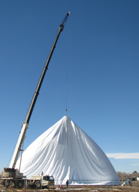
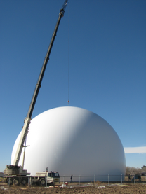
Once the base of the radome had been completely attached to steel tie down rings on the concrete foundation, the dome inflation blowers were started. The radome reached its operating shape and inflation pressure over a period of approximately 25 minutes (Figures 6a and 6b).
 |
 |
Offset Feed Antenna Data Example
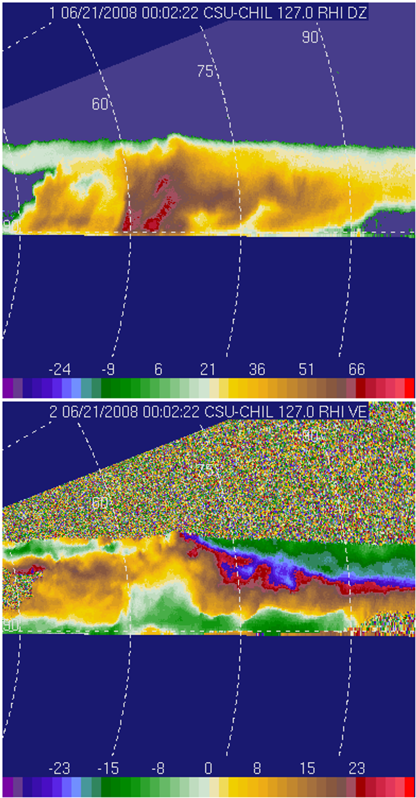
Following the basic installation of the new antenna and radome, the CSU-CHILL electronics trailers were moved into their new positions and the associated cable and waveguide runs were installed. Once these activities were completed, test operations to document the new antenna's performance were started in June, 2008. The data in the following RHI image was collected during one of these test operations. When the center-fed antenna was in use, side lobe-induced "smears" would typically appear above the true echo top in RHI scans done through strong echo core regions. These artifacts were caused by the spurious signals that were received when sidelobe radiation continued to illuminate the storm after the antenna's main beam had cleared the true storm top. Due to the substantially reduced sidelobe levels achieved by the dual offset feed design, echo top smear artifacts are not present above the storm in the 21 June 2008 RHI data. (Note: The data in this plot is unedited; no thresholding or velocity unfolding has been applied to the original archived data).
Additional information on the performance of the offset feed antenna can be found here.
