Hail signature development
Conceptual Summary
The net forces acting on freely falling raindrops cause the drops to assume an oblate (flattened) cross sectional shape. This is increasingly true for larger diameter, faster falling drops. The intensity of signal backscattered to the radar is a function of the target's diameter in the polarization plane of the incident radar pulse. Thus, an oblate rain drop will return a stronger signal when it is illuminated by a horizontally polarized pulse vs. a vertically polarized pulse. [1] Differential reflectivity () is based on the ratio of the horizontally polarized return signal to the vertically polarized return signal (as expressed on a logarithmic scale). For oblate targets will be positive since the H/V power ratio will be greater than one. Some example drop photographs and the associated values are summarized below:
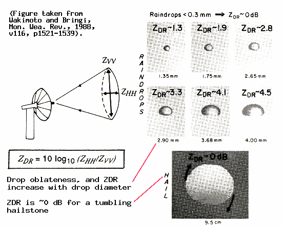
In contrast to raindrops, the ice structure of hailstones make them resistant to deformation. They also appreciably gyrate and tumble as they fall; on average these large amplitude motions tend to equalize the strength of the horizontally and vertically polarized return signals from hail. Thus, the observed in hail tends towards 0 dB.
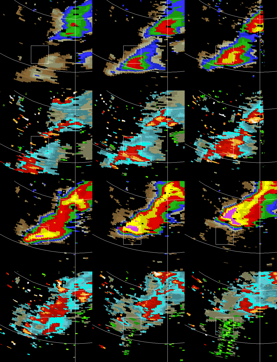
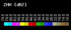
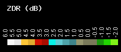
The image loop above shows a series of reflectivity and differential reflectivity images from 0.5 degree elevation PPI sweeps at approximately 2 minute time intervals. Over the course of the loop, the values within the 5 km x 5 km box region decrease rapidly from ~ +3.5 dB ~0 dB as hail replaces rain as the dominant precipitation component. A negative artifact also appears down-range of the main precipitation core in the later frames. The use of a 10 dBZ threshold and a spatial variability (texture) filter removes most of the artifact echo from the reflectivity image frames. The down-range location of this feature is due to the the extra signal path length that is added when three body scattering is active. The basic three body scattering path is illustrated below:
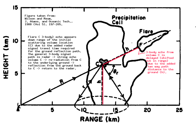
The effects of the three body scattering path upon are presented in [2]. Their analyses indicate that values are typically negative in the three body scattering artifact at low elevation angles. This is consistent with the patterns in the image loop.
VCHILL
Main article: VCHILL
References
- ↑ Aydin, K., T. A. Seliga, and V. Balaji, 1986: Remote sensing of hail with a dual linear polarization radar. J. Climate and Appl. Meter., 25, 1475-1484.
- ↑ Hubbert, J. C. and V. N. Bringi, 2000: The effects of three-body scattering on differential reflectivity signatures. J. Atmos. and Oceanic Tech. 17, 51-61.
